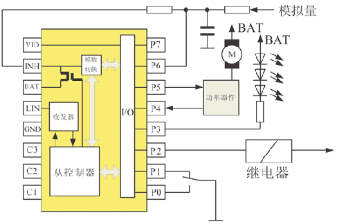
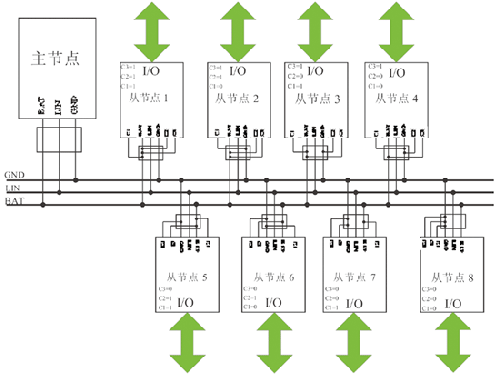
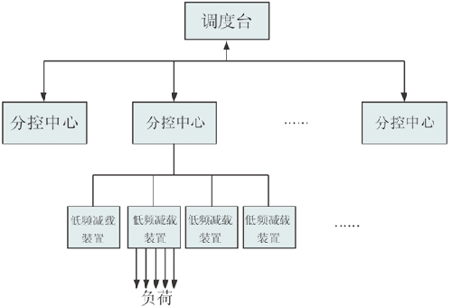
introduction This article refers to the address: http:// The LIN Local Interconnect Network is a serial communication network that connects simple control devices such as switches, displays, sensors, and actuators. It is primarily used to implement distributed electronic system control in automobiles. Because its main goal is to provide auxiliary functions for automotive networks (such as the CAN bus), it is usually used as a sub-network for applications that do not require bandwidth and versatility such as CAN bus, such as communication between smart sensors and brakes. . Significant cost savings can be achieved with the LIN bus, a low-cost serial communication model and corresponding development environment that has been developed by the LIN Association to reduce costs for automotive manufacturers and suppliers in developing and applying electronics. However, the application of LIN is not limited to the automotive field, and it should have a broad application status and prospects in areas such as industrial control. The technical features of the LIN bus include: (1) single-master, multi-slave architecture (no bus arbitration); (2) low-cost hardware based on the normal UART/SCI interface, low-cost software or as a pure state machine; (3) multicast with time synchronization Receive, slave nodes do not need quartz or ceramic oscillators; (4) deterministic signal transmission; (5) low-cost single-wire implementation; (6) rate up to 20 kbit/s; (7) bus length ≤ 40m; (8) guaranteed signal transmission delay time; (9) Selected data field length 0~8bytes; (10) flexible configuration; (11) data checksum security and error detection; (12) detection of faulty nodes in the network; (13) use of minimum cost semiconductor components (small size, single chip system) (14) Nodes can be added to the network without changing the hardware and software of the LIN slave node; (15) Usually there are fewer than 16 LIN network nodes. LIN2.0 bus technology The LIN 2.0 version reflects the definition of the LIN Association. By comparing the LIN1.3 and LIN 2.0 specifications, the two most significant changes are the standardized support for configuration and diagnostics, as well as the specified node capability files. In order to simplify the use of existing nodes. The working principle of LIN is based on the single master/multiple slave concept. In a LIN cluster, it consists of one master node and several slave nodes. The master node consists of a master task and a slave task. All other nodes contain only slave tasks. Figure 1 shows a typical LIN cluster, a master node and two slave nodes. The host task determines when and which frame to transmit, while the slave task transmits the frame data. Figure 1 single master multi-slave schematic The LIN2.0 message frame consists of a frame header and a frame response, where the frame header is transmitted by the host task and the frame response is transmitted by the slave task. Each message frame contains 2, 4, and 8 bytes of data. The structure of the message frame consists of a synchronous interval field (Break) followed by a 4 to 11 byte field, as shown in Figure 2. Table 1 Comparison of LIN bus and CAN bus performance Synchronization interval field The sync interval field can be thought of as an interrupt to indicate the start of a new message frame. The host task in the master node generates at least 13 significant states on the LIN bus, including the start bit and the sync delimiter. Synchronization field: The format is 0x55, which is represented by 5 falling edges among 8 bit timings. • Protection identifier: used to describe the meaning of the message data. A protection identifier field consists of two subfields: the 0th to the 5th bits are the identifier bits, and the 6th and 7th bits are the parity bits. The identifier has a total of 6 digits and ranges from 0 to 63. The identifiers can be divided into 4 categories: 0 to 59 (0x3b) message frames for signal transmission; 60 (0x3c) and 61 (0x3d) are used to transmit diagnostic data; 62 (0x3e) is an extended frame reserved for the user; 63 (0x3f) is reserved for future agreement subscriptions. • Data field: A message frame can “carry†0 to 8 bytes of data. • Checksum: The checksum is equal to the negation of the sum of all bytes of the data field. For a checksum that only computes all bytes of the data field, it is called a traditional checksum. If the checksum is to be calculated together with all bytes of the data field, it is called an enhanced checksum. It can be seen from Table 1 that the overall performance of the LIN bus is much worse than CAN, but the biggest advantage of the LIN bus over the CAN bus is that the implementation cost is relatively low, because LIN is not the low end of the performance, bandwidth and complexity of CAN. System, so LIN has a wide range of applications in these situations. Figure 3 UJA1023 configuration flow chart LIN slave node application design This article uses NXP's local interconnect network I/O accessory expansion chip UJA1023, which can help build a cost-effective, high-reliability in-vehicle LIN network. Although the original design of the chip was originally applied in the high-end car industry, due to its high integration and reliability, the chip can be used in the power industry. The UJA1023 is a stand-alone slave node that can be applied to local interconnect network (LIN) I/O. It can replace the basic components used in traditional electronic control units, which are used to control I/O. The UJA1023 includes a LIN 2.0 controller, an integrated LIN transceiver, and is also compatible with the LIN1.3 specification. It also includes eight I/O ports that can be configured via the LIN bus. The UJA1023 has an automatic bit rate synchronization circuit that can be synchronized with the master node from 1kbit/s to 20kbit/s, so a crystal is integrated into the chip. Input function · standard input pin; ·Local wake up; · Edge capture; · Analog signal input pin; • Switch matrix (used with the output pin). Output function Standard output pin, which can be configured as high-side drive, low-side drive, push-pull drive mode; • Periodic (cyclic) listening mode for local wakeup; · PWM mode, for example, driving the rear light of the car; • Switch matrix (used with input pins). Configuration process The UJA1023 can be configured in the form of a message chain through LIN command frames, ie, the main request command and the slave response command. The main request command sends configuration data, and the target slave node of the main request command will send the corresponding data to the master node as a response after receiving the command. Figure 3 shows the configuration flow of UJA1023, in which the orderly cooperation between the main request command and the slave response command is a concept of "handshake". UJA1023 application example Figure 4 General I/O port application It is shown in Figure 4. The single-chip UJA1023 has eight I/O ports for use as a general-purpose I/O port. In Fig. 4, P0 and P1 are used to read the value of the switching amount. P3 is used to drive the light emitting diode. P5 drives the motor through power amplification. P7 collects analog quantities, and P2 can also drive relays. Therefore, UJA1023 also has a “useful place†in relay protection. Multi-chip UJA1023 application Using the plug-in method, multiple pieces of UJA1023 are connected into a network form application by means of "single master and multiple slaves". A single-master multi-slave-based LIN network consisting of one master node and eight slave nodes is shown in FIG. As can be seen from the figure, each slave node has 8 I/Os, so the network has a total of 64 control ports. Multiple forms of multiplex control are available. Its characteristics are flexible application, convenient configuration, strong scalability, low cost and high reliability. It is worth mentioning that Figure 5 is only a sub-network. If more ports are needed, it is possible to perform multi-network expansion in the form of Figure 5, and the network and the network can be connected through a gateway. Figure 5 LIN network based on single master multi-slave mode This form is well suited for use in power system relay protection applications as shown in FIG. The low-frequency low-voltage load shedding device is designed to complete the 35kV system according to the power system frequency and voltage changes, and cut off the power load according to a predetermined control scheme. Figure 6 overall system block diagram The design idea of ​​the internal structure in each low-frequency load shedding device in Fig. 6 is referred to in Fig. 5. One device includes a sub-network based on single master and multiple slaves, that is, containing multiple pieces of UJA1023, and I/ of each chip. The O port drives a number of relays to control the relay to remove the load when necessary. Conclusion From the above analysis, it is not difficult to conclude that in the field of industrial automation, CAN can be used for control connections of sensors, digital I/Os, display and execution components that do not require high data transfer rates, but this can be wasteful. In this case, LIN's cost is cheap, anti-interference is strong, and the superiority of using a single-wire connection is reflected. In addition, the LIN bus can also be used in household appliances. For example, in a washing machine, the microprocessor measures the water level, the water flow, and the water temperature through the sensor of the LIN bus, and performs water supply and drainage control through an electric valve connected to the bus. Therefore, the application range of LIN bus technology is far from being limited to the automotive industry, but in other fields, it also has broad application prospects and practical significance that cannot be ignored. Stainless Steel Pressure Gauge Pressure Gauge Types,Different Pressure Gauge,Trerice Pressure Gauge,Fire Extinguisher Pressure Gauge Changshu Herun Import & Export Co.,Ltd , https://www.herunchina.com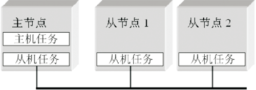
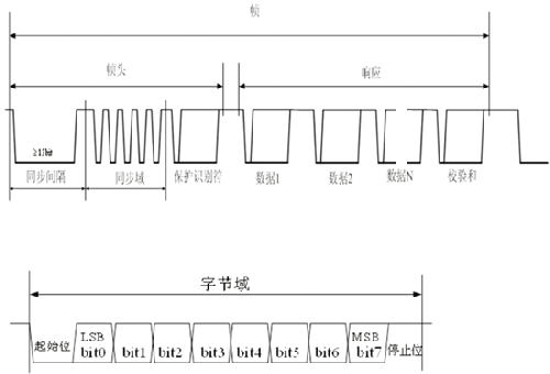
Figure 2 LIN message frame structure and byte domain structure 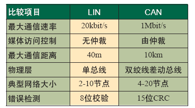
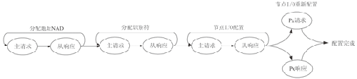
The LIN protocol is automatically processed by the chip. The settings of the node's address NAD and frame identifier (frame Identifier) ​​are daisy-chained or plug-in by the master request command and the slave response. The eight bidirectional I/O pins are configurable by LIN bus commands and can have the following features: