This chapter first gives a brief introduction to the component selection, installation procedures, debugging skills and key production methods of the self-made tube power amplifier. When you are ready to try, you can do it yourself.
Tube audio power amplifier, with its excellent playback sound quality, is widely favored by HiFi enthusiasts. Commercially available finished tube amplifiers cost thousands of yuan, or even tens of thousands of yuan. Such high prices are beyond the reach of most enthusiasts. Lovers say it well: "Do it yourself, get plenty of food." As long as you have certain electronic knowledge and certain hands-on ability, it is not difficult to make a cheap tube amplifier. Compared with transistor power amplifiers, tube power amplifiers seem to be huge and complex, but when you understand the working mode of the tube circuit, you will find that the tube persuasion circuit is relatively simple compared with the transistor discrete component power amplifier, and the number of components used is much less. In addition to the difficulty in making the output transformer self-made, as long as the other components are properly selected and the circuit is well debugged, a beautiful tube amplifier will be born in your hand.
Section 1 Assembly and welding skills of tube power amplifier
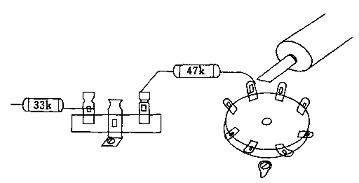
1. Scaffold welding method Many well-known tube power amplifiers at home and abroad have used scaffolding welding methods in the past and present. Because, the advantage of the scaffolding connection method is that the wiring can take a shortcut, so that the wiring is closest to achieve reasonable wiring. In addition, the number of components of the tube power amplifier is not large, and the volume is large. With the help of the component pins, it can be overlapped, reducing the disadvantages caused by too many leads. As long as the layout is reasonable, it is easy to receive better results. Figure 8-1 is a schematic diagram of scaffolding connection.
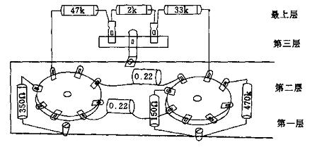
The scaffolding method generally divides various components in the power amplifier into 3-4 layers, and the step of installing components is from bottom to top. The ground wire and the filament trace are generally placed near the bottom layer of the bottom plate, and the ground wire is close to the bottom plate and maintains the best contact; the second layer is mostly the components where the cathode and grid of each tube are grounded. Note that the related components of the same tube cathode and grid are preferably grounded at the same point; the third layer is the coupling capacitor and other components between the amplifier stages; the uppermost layer is the resistance and capacitance components connected by high-voltage overhead connection. The high voltage components placed on the upper layer can effectively prevent the interference caused by the high voltage electric field on all levels of circuits.
2. One-point grounding One-point grounding is an important measure in the wiring of the tube power amplifier circuit. Figure 8-2 is a schematic diagram of one point grounding.
It is particularly important for the grounding of components in the input stage and voltage amplification stage. Components that need to be grounded at one point mainly include gate resistance, cathode resistance and bypass capacitor. It is best to use only the component leads for direct welding, and try not to use wires, otherwise AC noise will be easily generated.
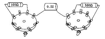
The gate resistance has the strongest sensitivity, so for the gate resistance with a small power consumption in the previous stage, the smaller the volume, the better. A small volume resistance of 0.25-0.5w is suitable. One end of the resistor should be directly welded to the tube base; the other end is directly connected to the ground. If it is difficult to ground at the same point due to component size or position, it can also be connected to the same thick ground line. Figure 8-3 is a schematic diagram of the near-end grounding.
3. Welding method Due to the large size of the parts of the tube power amplifier and the direct connection of the grounding wire to the metal bottom plate, the heat dissipation during welding is strong. Therefore, an internal heating electric iron of about 50W must be used during welding to ensure sufficient solder melt. However, the 25W electric soldering iron generally used for soldering transistor elements has insufficient heat, which is prone to false soldering or de-soldering.
Flux used in soldering should be rosin or first-grade neutral flux, avoid using acid flux. Because acid flux not only has a corrosive effect, but also causes circuit leakage.
For the welding of general components, it is best to maintain an inclination angle of about 45 degrees between the electric soldering iron and the component, so that the contact surface is large, the heat is uniform, and it is easy to weld firmly. The welding time should generally be kept for 1-2 seconds. If the time is too long, the components will be easily damaged; the welding time of the grounding wire can be longer.
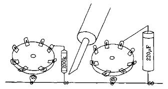
Before welding the component to the bracket, the component lead should be wrapped around the bracket or hooked into the hole, and then welded. For components, the oxide layer on the surface of the pin must be wiped clean with sand before soldering, and the solder must be plated before soldering. Figure 8-4 is a schematic diagram of the welding of the tube base and the bracket.
When welding the component and the ground wire, you must also wind the ground end and the ground wire first, or hook the hole of the solder piece, and then solder. When soldering, the soldering iron should be in contact with the solder joint for a longer time to ensure the soldering. For the components that need to be adjusted, lap welding can be used temporarily, and the welding will be wrapped around after the debugging is completed. Figure 8-5 is a schematic diagram of welding parts and ground.
For welding of overhead components, tweezers or needle-nose pliers can be used to clamp the components to avoid heat conduction and scalding fingers. When welding, you can first align the solder wire to the part to be welded, and then use the electric iron to fuse while welding, so that the welding quality is the best. Figure 8-6 is a schematic diagram of the welding of overhead components.
The quality of the solder wire also has a great relationship with the soldering quality. It is best not to use the general tin block and solder bar, and it is appropriate to use 1-3mm high-purity solder wire with a rosin core; the brand tube machine uses 2% silver Solder wire.
The voltage-dividing resistors and buck resistors of the DC high-voltage part generate a large amount of heat during use. Therefore, the overhead connection method must be used and the components should be placed on the uppermost layer to facilitate the heat dissipation. At the same time, it should also be noted that the wire through which the high-voltage current passes should not be close to or parallel to the other grid connections. It is best to use different colored wires to show the difference. And the distance of the wire should not be too long.
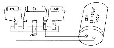
High-voltage decoupling resistors and capacitors must be welded close to the screen resistance, and if the ground terminal of the electrolytic capacitor is far away from the high-voltage ground terminal of the power transformer, a high-quality ground wire should be added to prevent the AC component in the filter capacitor The voltage amplifier tube of the previous stage. Figure 8-7 is a schematic diagram of the high-voltage component overhead connection method.
The over-bridge method between the bracket and the lamp holder mainly solves the coupling of the screen element with a longer span. Do not solder the components with large potential difference on the same bracket to avoid unnecessary interference. Figure 8-8 is a schematic diagram of the overhead connection between the bracket and the tube base.
The screen and gate components of the tubes at all levels should be kept as far away as possible. The components of the screen circuit of the latter stage must not be close to or parallel to the gate components of the previous stage.
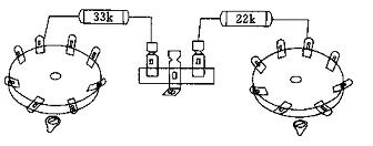
The resistor to be connected in series with the screen or grid circuit of the power amplifier tube should be directly welded to the screen or grid terminal of the electron tube base. Longer wires are connected. Figure 8-9 is a schematic diagram of the self-overhead connection of the tube base.
The connection between the power amplifier tube screen and the curtain grid circuit generally does not require a bracket, and is directly connected from the lamp holder, and is connected to the primary side of the output transformer through the bottom plate at the shortest distance, and the bracket cannot be used to bypass. This will not only increase the loss, but also affect the pre-amplifier.
Section 2 Installation Steps of Tube Amplifier
In addition to high-end models with discrete channels, most modern tube amplifiers are combined stereo amplifiers. The stereo amplifier is taken as an example to introduce its installation procedure.
According to the pre-designed status, first install various small parts. Such as tube sockets, switches, potentiometers, input and output terminals, sockets, wiring brackets, grounding lugs, etc. are installed one by one.
The tube lamp holder must recognize the direction shown in the figure when installing, so as to keep the wiring distance closest. Pin identification, you can point the tube pin towards you. When using a porcelain eight-pin lamp holder for power amplifier tubes, start from the center of the notch and clockwise, respectively, pins 1 → 8; when the preamplifier and push tube are nine-pin lamp holders, start from a larger opening , Clockwise, are pins 1 → 9 respectively. The pin identification of the special tube base is mostly identified under the specific mark according to the above method.
The left and right channel output transformers, power transformers, choke coils, etc. are relatively bulky. When installing and welding various parts, the bottom plate should be turned on all sides, which is easy to damage the exterior paint. It should be completed after welding all the resistance and capacitance components and wiring. Reinstall. When installing the power transformer and the output transformer, a spring washer must be added to the screw to make it difficult to loosen to prevent vibration between the transformer and the bottom plate after being energized, thereby causing eddy current loss and hum.
1 Reasonable grounding method The grounding wiring in the tube power amplifier has an important influence on the signal-to-noise ratio of the power amplifier and the quality of the electrical performance. Especially in the multi-stage amplifier with higher gain, the layout of the ground trace is particularly important. Because the ground wire in the power amplifier has a dual role, it is both a DC voltage and current supply circuit and a path for audio signals. The magnitude of the DC voltage and current passing through and the strength of the AC signal are also different.
Although all the ground loops in the power amplifier are measured with a multimeter, the resistance value is 0Ω, but for AC signals, there is still a potential difference between the grounding paths. If a high-frequency microvoltmeter is used for measurement, the potential difference between them can reach more than a few microvolts. In a high-gain multi-stage amplifier, if the grounding wiring is not properly arranged, if a few microvolts of AC clutter signals are mixed in the high-gain input terminal, after the multi-stage amplifier is amplified step by step, the signal noise to the amplifier will be Than bring a great impact.
There are currently two popular grounding methods: busbar grounding and single-point grounding.
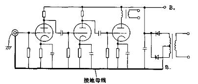
The busbar grounding method of the power amplifier is to use thick bare copper wires or silver-plated copper wires with a diameter of about 1-1.5M as the grounding busbars, which are arranged on the bottom plate of the power amplifier in the order of the nearest position of the tubes of the amplifier. Generally, it goes from the input terminal to the first stage, then to the inverting stage, pushing the amplifier stage, power amplifier stage, and finally to the ground terminal of the power transformer. The order of the grounding tracks must not be reversed between the previous stage and the next stage. The ground traces of the stereo amplifier must be strictly separated from the left and right channels, and be arranged in order. At the same time, it must be noted that the high-current ground wire at the output end must not directly communicate with the low-current ground wire at the input end. Figure 8-10 is a schematic diagram of the busbar grounding method.
The single-point grounding method is generally used in the input stage of high-gain amplifiers, or when part of the power amplifier adopts a circuit board, the principle of its ground wiring must also be arranged in order of the front and back stages of the power amplifier stage, and the front stage and the back stage must not be reversed .
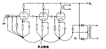
The single-point grounding method emphasizes that the ground of each stage must be connected to the same ground point (that is, we often say "one-point grounding"), where the gate resistance, negative voltage resistance and bypass of the cathode The passage of the capacitor is particularly important, and no wires are allowed to exist between the two. Because there is inevitably resistance in the wire, the potential difference may exist. For a highly sensitive amplifier, it is equivalent to connecting an AC power supply between the cathode and the grid of the amplifier tube. After step-by-step amplification, serious AC will be generated. sound.
The shielding isolation layer of the input terminal must be grounded at the same ground point of the preamplifier. The outer shielding shell or input terminal shell should communicate with the power amplifier shell. Figure 8-11 is a schematic diagram of single-point grounding.
The single-point grounding method and the busbar grounding method are not absolutely separate, and can generally be mixed. For example, the single-point grounding method is used in the highly sensitive front stage, and the busbar grounding method can be used at the power amplifier level and power filter level.
For the power amplifier with pre-amplification stage, the number of amplification stages can reach 5-6. In this way, the sensitivity at the MIC microphone or AUX pickup input is extremely high, which can be as high as 3-5mv. If a weak noise level is mixed into the input terminal, even if the input terminal noise level is only 0.01mv, after multi-stage amplification, if the useful signal output voltage increases from 3mv to 30v, the noise level will also be from 0.01mv, It is amplified to 0.1V. In this way, the signal-to-noise ratio of the power amplifier is close to 50dB, which will cause great interference to the output signal.
For the 3-4 stage power amplifier, the input sensitivity is 0.3-0.5v. If the input stage is also mixed with a noise level of 0.01mv, after a small number of stages of amplification, the useful signal is amplified by 100 times. The noise level is amplified to 1mv. The signal-to-noise ratio of the aircraft has reached 80dB, so it is still acceptable.
For high-sensitivity multi-stage amplifiers, due to the large number of amplification stages and high gain, we must not wait for weak noise signals, so high-quality amplifiers often take circuit isolation measures. For example, in a power amplifier, the front stage and the rear stage are separated, so that the stage amplification and the rear stage amplification form a loop, and then the front and rear stages are connected by a multi-core plug.
In addition, for the MIC sound input with high sensitivity, in order to prevent noise level interference, low-impedance, balanced input methods are often used, and shielded isolation devices are often provided at the input to separate the front-stage amplification. It can effectively reduce the interference of noise.
2 AC power cord wiring method The AC power wiring in the amplifier, especially the high-current AC filament wiring, if the wiring is improper, electromagnetic fields will be radiated outward, causing hum interference to the amplifier.
The waveform of the 50Hz alternating current is a sine wave. When the load is connected, the current on the AC wiring loop changes with the period of the alternating current. The greater the current in the AC trace, the greater the electromagnetic field radiated outward. If unidirectional wiring is used, the external radiated electromagnetic field will induce other wiring and components in the power amplifier to produce severe induced hum.
If the AC power cord or AC filament in the power amplifier is routed with double strands, due to the distributed capacitance between the parallel lines, although some electromagnetic fields can be bypassed, the interference cannot be cleared.
If the AC power wiring in the power amplifier is twisted with double-stranded wires, because the currents of the two twisted AC wirings are opposite to each other, the electromagnetic fields radiated by the AC power can be cancelled each other, so the disturbance of the external electric field can be eliminated ( (Figure 8-12)
3 Layout of high-voltage power supply Taking stereo amplifier as an example, the wiring principle is that the left and right channels should be strictly separated. The grounding trace is placed on the bottom layer of the bottom plate and adopts the busbar grounding method. The grounding lines of the left and right channels are divided into two paths and are arranged in order of the front and rear stages of the amplifier. Both the AC filament wiring and the AC power wiring are twisted in a two-wire manner to reduce the radiation of external electromagnetic fields.
The DC high voltage of the stereo power amplifier is up to about 400V. In order to prevent the radiation of the high-voltage external electric field, a wiring bracket must be used to place the high-voltage power supply line on the uppermost layer of each component, that is, the so-called overhead connection method. High-voltage power supply lines should also pay attention to avoid the gate grid wiring of the electron tube as much as possible to prevent the induction of hum and howling.
The total current of stereo high-voltage DC high-voltage power supply is generally about 0.4A, and its static operating current and operating current at full signal are less fluctuating, so the capacity of the high-voltage filter capacitor does not need to be too large, generally tens of microfarads to hundreds Microfabrication can be satisfied. The transistor power amplifier works under the condition of low voltage and large current, and the current fluctuates greatly during static and full load. Therefore, a filter capacitor of thousands to tens of thousands of microfarads must be used to meet the requirements.
The pre-stage filter capacitor is usually 100-470uF, which can be fixed to the base plate with a capacitor clamp ring or thick copper wire. It is a sub-high-voltage power supply after being depressurized by the glaze resistor. It is specially used for pre-amplification and driving amplifier stages. Its decoupling filter capacitor can be combined with CDZ, and the capacity is only 20-30uF. .
4 Assembly of components After the wiring work is finished, you can start to install and weld the resistors and capacitors and other components on the bases of all levels. The self-made power amplifier mostly adopts the scaffolding welding method. The method of scaffolding can be routed nearby to meet the requirements of reasonable wiring. For easy identification, the connecting cables used in the power amplifier are generally used in red for DC high-voltage lines, yellow or orange for the grid connection, green or blue for the grid connection, and brown or black for the cathode connection.
The gate resistance, cathode resistance and bypass capacitance of each amplifier stage must be grounded at the same bus bar nearby. The gate resistor has the smallest power consumption. In order to prevent induced noise, the smaller 0.5W metal film color ring resistor can be used as the best.
The gate impedance of the electron tube is very high, and the sensitivity is also high. Therefore, the coupling capacitance and resistance of the gate circuit cannot be close to the components of the high-voltage circuit and the screen circuit to prevent the interference of external radiated electromagnetic fields. At the same time, the coupling capacitor with polarity must be recognized when welding, the positive terminal is connected to the screen electrode of the electron tube, and the negative terminal is connected to the grid of the electron tube. When the connection is reversed, it will cause ills due to increased leakage and lowered withstand voltage. In addition, pay attention to the withstand voltage of the coupling capacitor must be above 400V.
The interstage matching capacitor has a great relationship with the sound of the power amplifier. Capacitors with low dielectric loss and fast conversion rate can be selected, such as CBB polypropylene, CB polystyrene, CZM oil-immersed capacitor, CZ30 paper dielectric capacitor, etc. If you choose WIMA, SOLEN, MKP and other audio special metalized non-inductive capacitors, it is better.
The input tube grid has high sensitivity, and the lead of the related volume control potentiometer is long. To prevent interference of the clutter signal, a metal shielded isolation wire must be used. The outer layer of the metal braided wire must be grounded at the cathode of the input tube. When entering the ground, do not connect the grounding terminal to the output terminal of high current.
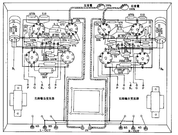
Figure 8-13 is a schematic diagram of the arrangement of stereo power amplifier components.
The third part of the amateur debugging of the tube power amplifier is completely installed and welded. The new installation and the circuit diagram should be carefully compared. If there is any leakage or connection error, the components between the screen and the grid should not be tightly attached, and the wires must not be Parallel, all checks are correct, you can start the initial adjustment.
For the friends who first install the tube power amplifier, because the working voltage of the tube power amplifier is much higher than that of the transistor power amplifier, and its metal bottom plate is the negative electrode, in order to prevent inadvertently being shocked, it is best to operate with one hand during debugging and measurement. Do not hold the bottom plate with the other hand. After the power is turned off, there are still stored high-voltage charges in the high-voltage filter capacitors in the machine. Once they touch the capacitor leads, they will be shocked. Each time after the power is turned off, the positive electrode of the capacitor should be discharged to the bottom plate through a low-resistance resistor (direct short-circuit to ground will generate sparks), and then detect other components.
Before commissioning, the power amplifier has not entered the normal working state. In order to protect the speaker from accidental damage, a dummy load must be connected to the output terminal instead of the speaker. The resistance value is 8-16Ω / 20W. Three minutes after turning on the machine, pay close attention to whether there are abnormal phenomena such as flashover or smoke in the machine, and whether the temperature rise of all parts is normal.
1 Measure the voltage at all levels Measure the AC voltage value of each level of the power transformer first, and then measure the DC high voltage after all the measurements are correct.
Beginners can first clamp the multimeter's negative pole with an alligator clip and a ground wire or a bottom plate, and then use a positive pole to measure the voltage at all levels.
The DC high voltage should be about 1.4 times the AC high voltage under light load. When measuring high voltage, first set the multimeter to DC 500V. If the AC high voltage is 320V, the DC high voltage at both ends of the filter capacitor after bridge rectification should be about 440V.
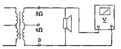
2 Measure the voltage of each electrode screen Figure 8-14 is a schematic diagram of measuring the voltage of each screen electrode.
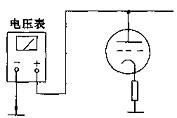
For simplicity, measuring the voltage of each screen electrode can be carried out according to Figure 8-14. The exact value of the screen voltage should be the voltage between the screen and the cathode of the tube.
For example, the screen voltage of the power amplifier tube to ground is about 400V, and the voltage drop of the cathode resistance to ground is only a few volts, so it can be ignored. However, for the screen-inverted split-phase inverter, since the load resistance of the screen electrode and the cathode are both 22kΩ and the voltage drop to ground is large, the voltage between the screen and the cathode must be measured.
3 Measurement of grid negative pressure Figure 8-15 is a schematic diagram of grid negative pressure measurement of the power amplifier tube.
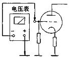
The negative pressure of the grid of the power amplifier tube changes with the size of the push signal. When measuring the negative bias voltage of the self-sufficient gate of the power amplifier tube, it must be measured after the audio signal is injected. The accurate grid negative pressure value should be the value between the grid and the cathode. Because the voltage drop of the power amplifier tube to the ground is small, it is often negligible.
If the negative voltage difference between the two power amplifier tube grids is large, first see if the front stage push voltage is balanced, and then calibrate by adjusting the grid resistance.
If the cathode voltage differs greatly, you should first understand the matching situation of the power amplifier tubes, and can exchange each other for a trial. Finally, you can balance the two tubes by adjusting the resistance of the cathode resistance.
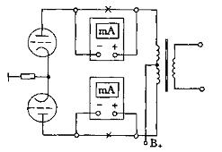
4 Measurement of the screen current of the power amplifier tube Figure 8-16 is a schematic diagram of the screen current measurement.
The push-pull power amplifier of the electronic tube is not as strict as the transistor of the power tube, because the amplification factor of the transistor of the same model will also be greatly different, and the parameter consistency is not as good as the electronic tube. As long as the tubes use the same brand and products of the same period, their amplification characteristics are basically the same.
For the electronic tube, if it is a tube type that is stored for a long time, the matching work of matching the power amplifier tube is essential. The simpler method is to measure the quiescent current and full signal current of the power amplifier, the two are basically balanced, that is, they can be paired.
When measuring, first connect the connection point of the power amplifier tube screen and the output transformer with an electric soldering iron, pull out the multimeter to the DC current 250-500mA file and string it into the screen circuit, generally measured when there is no driving signal in the previous stage The quiescent current of the tube is obtained, and the measured value when the driving signal is strongest is the full-load signal current.
If the static current of the two push-pull power tubes is not much different from the full-load signal current, you can calibrate by adjusting the cathode resistance and gate bias resistance of the power amplifier tube to achieve a basic balance of the two tubes. If the current values ​​of the two tubes differ greatly, only the new tube must be replaced.
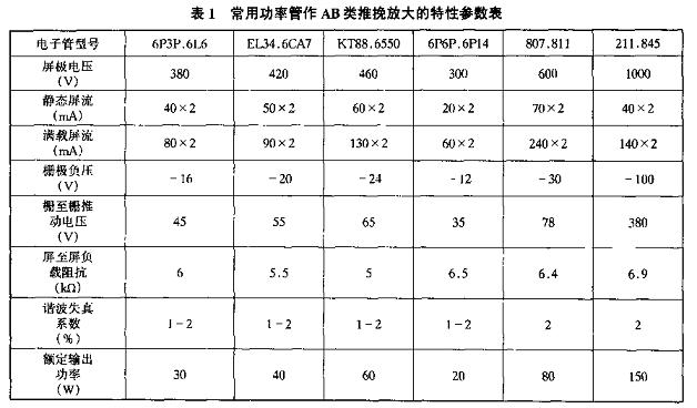
Table 8-1 is the characteristic parameter table of common power tubes used for class AB push-pull amplification.
5 Adjustment of negative feedback resistance After the initial adjustment of the whole machine, connect the negative feedback resistance between the upper input stage and the output stage, the resistance value is generally between 12-24kΩ, and the negative feedback amount is controlled between 10-20dB: negative After feedback access, the most obvious feeling is that the background noise is greatly reduced. If the negative feedback resistor is connected, the output power increases, or accompanied by howling, it means that the output transformer coil phase is reversed, and the transformer coil phase should be replaced.
6 Input audio signal Turn off the power and remove the dummy load, connect the speaker, and then adjust the volume potentiometer to the minimum volume position. Inject a signal from the input for trial listening. The general input sensitivity of the amplifier is 0.3-0.7V. It can inject the line output signals of CD, VCD, DVD, recording deck, tuner, etc., the volume potentiometer is gradually adjusted from small to medium volume, and the trial listening is continued for about 1 hour. If there is no abnormality in each part, it can be considered as initial installation smoothly.
However, many problems inevitably occur in the general initial installation, such as hum, noise, distortion, etc., so you can further adjust the polyphony
The fourth section of the complete adjustment and fault detection of the tube power amplifier
After the initial adjustment of the whole machine, such as when there is a series of abnormal phenomena such as silence, hum, noise, low sound, distortion, etc. when the audio signal is input, it means that there are some faults in the power amplifier, so it must be carefully adjusted. Find out the fault, so as to obtain satisfactory sound effects,
1 Silent fault check The voltage and current of the whole amplifier are correct, but the speaker has no sound after the audio signal is injected from the input terminal, and it should be checked step by step.
First turn off the power of the power amplifier, and remove the speaker speaker wiring to ensure that the speaker and speaker cable are intact. Use a multimeter to measure whether the output terminals of the power amplifier have poor contact. Then check the plugs, sockets, potentiometer contacts of each input terminal and the shielding layer and core wire of the audio signal line for short circuits and open circuits. If it is correct, you can turn on the power supply of the power amplifier, place the center arm of the volume potentiometer in the middle position, and directly touch the grid of the input tube with a single-handed rotary chisel. In general, fault tracing mostly adopts the method of self-output terminal and step-by-step forward detection. This method can find the fault point quickly.
First check the loop between the power amplifier stage and the output transformer, and then check whether the power amplifier pins are pressed incorrectly. A 0.1uF DC blocking capacitor can also be connected to directly input a strong audio signal at the input end of the power amplifier stage. If the output signal is normal, the audio signal through the DC blocking capacitor can be directly sent to the gate of the amplifier tube, if the speaker has A normal sound is emitted, indicating that the fault is between the input stage and the inverting stage. Care should be taken to find out if there is any connection or open circuit in the input circuit stage.
Because the amplification factor of a single power amplifier tube is very limited, and often requires a strong driving voltage, when the sound source signal is injected into the grid of the power amplifier tube, there is only a slight sound in the speaker;
2 Severe hum fault analysis The sonic level of the tube power amplifier is more significant than that of the transistor power amplifier. The signal-to-noise ratio of the finished transistor power amplifier can reach 90-100dB; the signal-to-noise ratio of the domestic brand Spak tube power amplifier is 85dB, and it is generally produced by amateurs. The signal-to-noise ratio of the tube power amplifier reached 70-80dB has been satisfactory. It is normal to have a slight AC sound in the speaker when the volume of the self-made tube power amplifier is turned on. If the exchange sound is significant, it should also be found and eliminated as a kind of fault.
Turn off the volume potentiometer first. If the exchange sound decreases, the volume increases, and the exchange sound also increases, indicating that this fault occurs at the input stage. The most common reason for this phenomenon is that the metal shield of the input signal is grounded improperly, the volume potentiometer shell is not well grounded, the input tube grid and cathode ground loop are not properly arranged, and there is a slight leakage between the filament and the cathode of the input tube Phenomena, etc.
The gate resistance of the inverter and the drive stage is poorly connected, or the resistance value is too large to easily produce hum. Improper location of the coupling capacitor device between stages, induced interference from stray electromagnetic fields of other nearby components, can also cause hum, and you should carefully check whether the component layout and grounding point are reasonable.
After the pre-stage fault is eliminated, the pre-amplifier tube and the push-level tube can be unplugged, leaving only the power amplifier tube. If there is still a large amount of hum, it may be caused by the insufficient voltage of the filament of the power amplifier tube or the slight leakage of the old tube. Use a voltmeter to measure the filament voltage first. If the voltage drop is large, remedial measures should be taken in time. If you suspect that the quality of the power amplifier tube itself is defective, you can try another power amplifier tube.
The power part has the highest probability of causing hum. Insufficient capacity of the filter capacitor or leakage current will cause hum. When the first-stage filter capacitor is severely leaked, not only the exchange sound is loud, but also the DC high voltage output is low; when the second-stage filter capacitor is severely leaked, not only is the exchange sound loud, but also accompanied by howling.
Poor welding or poor grounding of the lead between the static shielding isolation layer between the primary side and secondary side of the power transformer can also cause hum. If the rewinding cannot be disassembled, the remedy is between the AC power inlet and ground A capacitor of more than 0.01uF / 400V is connected between them, which can play a certain inhibitory role; but the disadvantage is that there will be a slight numbness phenomenon when touching the cabinet of the power amplifier.
In addition, when the power transformer or choke is in the device, if the iron core directly contacts the bottom plate, the eddy current magnetic field generated in the core will extend to the iron bottom plate, thereby inducing hum. Therefore, when installing the power transformer, it is necessary to install a shockproof gasket between the transformer and the bottom plate; the high-end tube amplifier uses a fully sealed cover, which can completely eliminate the hum.
3 Noise failure analysis When the power amplifier is playing normally, abnormal noises such as irregular clicks or squeaks can be divided into: internal noise and external noise;
Figure 8-17 is a schematic diagram of internal noise interference of the power amplifier:
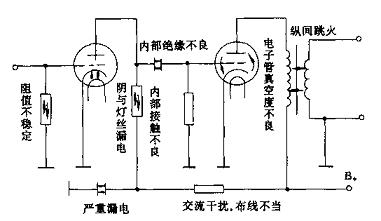
1) Internal noise interference When the power transformer, output transformer, high-voltage choke coil and other internal layers of the amplifier are poorly insulated, after high-voltage electricity is passed in, due to the increase in potential difference, there will be interstage flashover, which will cause the whole machine Noise interference.
The electronic tube selected by the power amplifier, such as a collection or old product, has a long-term poor vacuum, and leakage of electricity between the cathode and the filament can cause noise interference.
When poor quality carbon resistors are used, the resistors are unstable due to uneven internal resistance and poor contact, and intermittent noise will be generated after power-on operation.
When the coupling capacitors, filter capacitors and other internal insulation selected in the power amplifier have poor internal insulation or serious leakage, all kinds of noise interference will occur.
2) External noise interference Figure 8-18 is a schematic diagram of the external noise interference of the power amplifier.
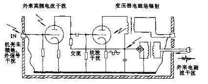
In the circuit with higher sensitivity, such as MIC sound transmission and AUX pickup input, it is often interfered by external high-frequency electromagnetic waves. After the interference signal is amplified step by step through the input tube grid, it will form a serious noise interference.
Various modern high-power electrical equipment, dimming and speed control equipment can also enter the power supply of the power amplifier through the AC power grid, causing various electromagnetic wave interference.
The power transformer, output transformer, etc. in the power amplifier, when the power is turned on, will also produce various electromagnetic field radiation interference.
In addition, such as poor grounding of the input socket, improper wiring and layout, all kinds of external clutter signals will be connected to all levels of the power amplifier through the signal line and the high-voltage line in the machine, and will be amplified after each step to form interference noise.
C) Noise suppression measures Figure 8-19 is a schematic diagram of anti-clutter interference.
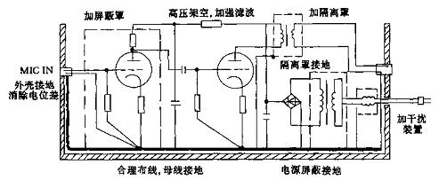
In order to prevent the high-sensitivity amplifier from being interfered by various clutter inside and outside, and to improve the signal-to-noise ratio of the amplifier, the following measures can be taken:
Input stage plus shielding device. For the Canon socket with high-sensitivity microphone input, its shell is grounded to the chassis and the bus bar inside the machine, and the signal ground wire should be grounded outside the input pipe. And low-impedance, balanced input mode can be used, so that the noise level and the interference of various clutter signals can be effectively eliminated. In order to prevent the radiation of electromagnetic fields, the power transformer and the output transformer should be added with an isolation cover or a closed shell, and the shielding cover should be grounded. The grounding wire can adopt the busbar grounding method. For high-sensitivity pre-stage components, one-point grounding should be used to reduce potential difference and prevent noise level interference. High-voltage wiring should try to avoid the grid of each tube. Adopt overhead connection of high-voltage components, and strengthen the filtering and decoupling of high-voltage DC power supply. The capacitors and resistors used in the machine should be of reliable quality and carefully tested before being used on the machine. In order to prevent external electromagnetic waves from penetrating into the machine through the power supply network, the product power filter can be used if possible, or a self-made anti-interference network coil can be inserted into the AC power inlet circuit. The simple manufacturing method of the coil is to use two high-frequency magnetic cores, each with 30-50 turns of enameled wire with a diameter of 0.2-0.5mm, and respectively connected in series in the loop of the AC incoming line, which can have a certain effect of suppressing external interference. Section 5 Performance Test and Improvement of Self-made Amplifier
1. Test and adjustment of output power
1 Simple test method of output power After the power amplifier is assembled and debugged, I always want to know the output power of this machine. When there is no formal test instrument, a multimeter can be used to make a simple estimation.
Figure 8-20 is a schematic diagram of using a multimeter to estimate the output power.
Inject the audio signals of CD, VCD, recording deck, etc. from the input of the newly installed amplifier, and put the volume potentiometer at the maximum position.
Set the multimeter to 25V or 50V AC voltage. Because the measured voltage is the AC signal voltage, the test leads are not positive or negative. When measuring, connect two test leads in parallel to the output terminal of the power amplifier or both ends of the speaker. At this time, the needle of the multimeter keeps oscillating with the strength of the audio signal, and record the voltage value when the needle oscillates to the maximum.
The calculation method is as follows:
Rated output power P ï¼ V2 / Z
Where: V is the measured output voltage, Z is the load impedance value.
Under a 4Ω load, if the measured maximum AC voltage value is 10V or 12V, the rated output power of the power amplifier is:
P1 ï¼ V2 / J ï¼ 102/4 ï¼ 25W
P2 = V2 / J = 122/4 = 36W
Under 8Ω load, if the measured maximum AC voltage value is 12V or 16V, the rated output power of the power amplifier is:
P1 ï¼ V2 / Z ï¼ 122/8 ï¼ 18W
P2 = V2 / Z = 162/8 = 32W
Due to the output level of CD, VCD and other music signals, it is weaker than the continuous sine wave signal of the audio signal generator. The value measured with a multimeter is close to the effective value of the AC voltage, so it can be considered as the rated output power. If it is measured by peak power, it can be increased by 4 times, that is, when the rated power is 30W + 30W, the peak power can reach 120W + 120W.
2 Measures to increase output power After the above simple estimation, the output voltage of the power amplifier does not reach the required value or the output voltage is higher, but the distortion and noise are significantly larger, the following debugging can be carried out:
We know that the output power of a general audio amplifier has two indexes: maximum output power and maximum undistorted output power. The maximum output power indicates the maximum load capacity of the power amplifier; the maximum undistorted output power indicates the power amplifier's undistorted amplification capacity. For the tube power amplifier, understanding the maximum undistorted power is more worthy of attention; therefore, while enhancing the output power, the distortion index and other performance parameters of the whole machine must be taken into account. It is not advisable to pursue the output power blindly.
Under the premise of ensuring that the degree of distortion does not decrease too much, the methods for increasing the output power include the following measures that can be considered:
Reducing the resistance of the cathode resistance of the power tube increases the output current, and the output power can increase to a certain extent. However, due to the reduced negative feedback of the cathode resistance, the stability of the amplifier and other performance indicators must be affected.
Properly increasing the screen voltage of the power amplifier stage can increase the output power. However, the limit operating value of the power amplifier tube must be considered, and whether the withstand voltage of the power supply filter capacitor is large enough, and whether the dissipated power of the DC high-voltage loop's step-down resistor can meet the requirements. Properly increasing the driving voltage of the driving stage can also increase the output power of the whole machine. The measure is to reduce the resistance of the cathode resistance of the amplifier tube. Since the cathode resistance of the driving stage has a negative current feedback function, the reduction of the cathode resistance will reduce the amount of feedback, and will have a certain impact on the distortion coefficient and frequency response of the whole machine. Appropriate adjustment of the negative feedback of the whole machine can also effectively increase or decrease the output power of the whole machine. That is to adjust the resistance of the negative feedback resistor of the whole machine from the cathode of the input tube to the end of the output transformer.åŠ å¤§è´Ÿå馈电阻,会使负å馈é‡å‡å°ï¼Œè¾“å‡ºåŠŸçŽ‡å¢žå¤§ï¼Œä½†æ”¾å¤§å™¨çš„å·¥ä½œç¨³å®šæ€§å’Œæ€§èƒ½æŒ‡æ ‡ä¼šæœ‰æ‰€ä¸‹é™ï¼›å‡å°è´Ÿå馈电阻,会使负å馈é‡åŠ 大,输出功率会相应å‡å°ï¼Œä½†æ”¾å¤§å™¨ç¨³å®šæ€§æ高,频å“ã€ä¿¡å™ªæ¯”ã€å¤±çœŸåº¦ä¼šæœ‰æ‰€æ”¹å–„。过é‡çš„深度负å馈会使整机的转æ¢é€Ÿåº¦é™ä½Žï¼Œçž¬æ€å“应å˜å·®ã€‚æ›´æ¢ç”µå管
以上措施å‡æœ‰åˆ©æœ‰å¼Šï¼Œä¸èƒ½ä¸¤å…¨ã€‚较å¯é 的方法是更æ¢æ€§èƒ½æ›´å¥½çš„电å管。如输出功率放大管由6P3Pæ›´æ¢ä¸ºEL34ã€6CA7ã€KT88ç‰ã€‚æ›´æ¢ç”µå管,必须考虑到原æ¥çš„电æºå˜åŽ‹å™¨ã€è¾“出å˜åŽ‹å™¨ç‰æ˜¯å¦ç¬¦åˆè®¾è®¡è¦æ±‚。如å˜åŽ‹å™¨åŠŸçŽ‡ä½™é‡çš„大å°ã€é«˜åŽ‹ç”µæµçš„大å°ã€æ»¤æ³¢ç”µå®¹çš„è€åŽ‹é«˜ä½Žç‰å„项性能是å¦ç¬¦åˆè¦æ±‚。管脚的排列也è¦å¯¹åº”。
二ã€æ–½åŠ è´Ÿå馈改善放大器的性能 对现代高ä¿çœŸåŠŸçŽ‡æ”¾å¤§å™¨æ¥è¯´ï¼Œå¦‚何å‡å°åŠŸæ”¾çš„éžçº¿æ€§å¤±çœŸï¼Œæ高放大器的信噪比,拓宽频率å“应,是至关é‡è¦çš„。
é‡‡ç”¨æ–½åŠ è´Ÿå馈æ¥æ”¹å–„与æ高放大器工作的稳定性和å„é¡¹æ€§èƒ½æŒ‡æ ‡ï¼Œåœ¨å›½å†…å¤–é«˜ä¿çœŸåŠŸæ”¾ç³»ç»Ÿä¸å¾—到了广泛的应用。所谓“å馈â€ï¼Œå°±æ˜¯æŠŠè¾“出信å·çš„电æµæˆ–电压的一部分回é€åˆ°è¾“入端去调节输入信å·çš„一ç§æ–¹æ³•ã€‚åé€å›žè¾“入端的信å·å‰Šå¼±äº†è¾“入情å·ï¼Œä½¿æ”¾å¤§å™¨æ”¾å¤§å€æ•°é™ä½Žï¼Œç§°ä¹‹ä¸ºâ€œè´Ÿå馈â€ï¼Œå之,称为“æ£å馈â€ã€‚æ ¹æ®å馈信å·æ£æ¯”于输出电压还是电æµï¼Œå¯¹äºŽæ”¾å¤§å™¨æ¥è¯´åˆ™æœ‰ç”µåŽ‹å馈和电æµå馈之分。è¦æå‡ºçš„æ˜¯ï¼ŒåŠŸæ”¾æ•´æœºåŠ äº†æ·±åº¦çš„å¤§å›žçŽ¯è´Ÿå馈以åŽï¼Œè™½ç„¶æ”¾å¤§å™¨çš„性能æ高ä¸å°‘,但对放大器瞬æ€å“应ã€è½¬æ¢é€ŸçŽ‡ç‰æ€§èƒ½å´å¸¦æ¥äº†ä¸åˆ©çš„å½±å“。所以负å馈的è¿ç”¨å¿…é¡»æ°å¦‚其分ã€é€‚å¯è€Œæ¢ã€‚
1ï¼Œå¯¹æ”¾å¤§å™¨æ–½åŠ è´Ÿå馈的好处 å¯¹æ”¾å¤§å™¨æ–½åŠ è´Ÿå馈主è¦æœ‰å¦‚下作用
æ高了放大器的稳定性 放大器的稳定性主è¦åæ˜ åœ¨æ”¾å¤§å€æ•°ä¸Šã€‚放大器的放大å€æ•°ä¼šå‡ºäºŽç”µåŽ‹æ³¢åŠ¨ã€æ¸©åº¦å˜åŒ–ç‰åŽŸå› 而éšä¹‹å˜åŒ–ã€‚åŠ å…¥è´Ÿå馈åŽï¼Œå½“放大å€æ•°å‡é«˜æ—¶ï¼Œè´Ÿåé¦ˆç”µåŽ‹åŠ åœ¨è¾“å…¥ç«¯ä½¿è¾“å…¥ä¿¡å·å‡å°ï¼Œæ”¾å¤§å€æ•°éšä¹‹é™ä½Žï¼›å之,输入信å·å›žå‡ï¼Œæ”¾å¤§å€æ•°å¢žé«˜ã€‚由于控制信å·å–自输出信å·ï¼Œæ‰€ä»¥æ”¾å¤§å™¨å¯ä»¥ä½œåˆ°è¾“出ã€è¾“入“相辅相承â€ï¼Œä¿æŒåœ¨ä¸€ä¸ªç›¸å¯¹ç¨³å®šçš„工作状æ€ä¸‹ã€‚ 改善了放大器的频率特性 放大器的频率å“应,åæ˜ äº†æ”¾å¤§å™¨çš„æ”¾å¤§å€æ•°éšä¿¡å·é¢‘率的ä¸åŒè€Œæœ‰æ‰€å˜åŒ–。负å馈å¯ä»¥ä½¿æ”¾å¤§å™¨å› 频率å˜åŒ–引起的放大å€æ•°å˜åŒ–相对å‡å°ï¼›å°½ç®¡åŠ 入负å馈会使放大å€æ•°å‡å°ï¼Œä½†å´æ”¹å–„了放大器的频率特性,å³é¢‘å“展宽。 å‡å°äº†æ”¾å¤§å™¨çš„éžçº¿æ€§å¤±çœŸ 电å管是一ç§éžçº¿æ€§å™¨ä»¶ã€‚所谓éžçº¿æ€§æ˜¯æŒ‡ç”µå管输出电压与输入电压之间的关系ä¸æ˜¯ç›´çº¿å…³ç³»ï¼Œä¹Ÿå°±è¯´å…¶è¾“出ã€è¾“入特性曲线ä¸æ˜¯ä¸€æ¡ç›´çº¿ã€‚å½“ä½ åœ¨è¾“å…¥ç«¯è¾“å…¥ä¸€ä¸ªæ£å¼¦æ³¢ä¿¡å·æ—¶ï¼Œè¾“出信å·ä¸æ˜¯ä¸Žè¾“入信å·æ³¢å½¢ä¸€æ ·çš„æ£å¼¦æ³¢ï¼Œè€Œæ˜¯å‘生了畸å˜ï¼Œè¿™å°±æ˜¯è¯´äº§ç”Ÿäº†éžçº¿æ€§å¤±çœŸã€‚åŠ å…¥è´Ÿå馈åŽï¼Œè¾“出信å·çš„波形失真å馈到输入端,但由于失真的波形与输入端的波形相ä½ç›¸å,补å¿äº†æ”¾å¤§å™¨çš„失真,使输出波形得到改善。
æ¤å¤–,负å馈对放大器的输入ã€è¾“出阻抗也有一定影å“。
三ã€ç”µå管放大器常用的负å馈措施 图8-21是一ç§å•çº§ç”µåŽ‹è´Ÿå馈电路。
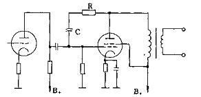
图8-21ä¸çš„RCè´Ÿåé¦ˆç½‘ç»œåŠ åœ¨æ”¾å¤§ç®¡çš„å±æžï¼Œå°†è¾“出信å·åé¦ˆä¸€éƒ¨åˆ†è‡³è¯¥ç®¡çš„æ …æžã€‚å› ä¸ºåœ¨å…±é˜´æžç”µè·¯ä¸ï¼Œç”µå管å±æžçš„电ä½ä¸Žæ …æžç”µä½æ£å¥½ç›¸å,故形æˆè´Ÿåé¦ˆã€‚æ …æžå› è´Ÿåé¦ˆåŠ å…¥è€Œä½¿è¾“å…¥ç”µåŽ‹é™ä½Žï¼Œæ”¾å¤§ç®¡çš„放大å€æ•°ä¹Ÿéšä¹‹é™ä½Žï¼›æ”¾å¤§å™¨å› è´Ÿè½½å˜åŒ–所引起的相ä½å¤±çœŸå’Œé¢‘率失真å‡å¾—到改善,其电压å馈é‡æ˜¯ç”±ç”µé˜»R与Cæ¥å†³å®šçš„。一般电路ä¸Rçš„é˜»å€¼ä¸ºå‡ ç™¾åƒæ¬§ï¼Œå®ƒä¸Žæ”¾å¤§å™¨çš„é¢‘çŽ‡æ— å…³ã€‚C的容é‡ä¸º0.01-0.1å·¦å³ï¼ŒC与放大器的频率特性相关,å¯ä»¥å¯¹æŸä¸€é¢‘段的信å·å®žæ–½è´Ÿå馈。
图8—22是一ç§çº§é—´è´Ÿå馈电路图。
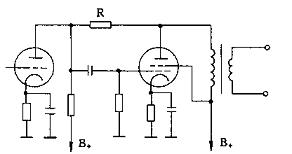
å°†åŽä¸€çº§æ”¾å¤§ç®¡å±æžçš„ä¿¡å·ï¼Œé€šè¿‡ç”µé˜»Rå馈到å‰ä¸€çº§ç”µå管的å±æžã€‚å› å‰çº§ä¿¡å·ç»æ …æžå€’相åŽï¼Œå‰çº§ä¸ŽåŽçº§ä¸¤ç®¡çš„å±æžç›¸ä½äº¦ç›¸åï¼Œè¿™æ ·å³ç»„æˆå±è‡³å±æžçš„è´Ÿå馈网络。å馈电阻R的阻值—般å–1—1.5MΩ。若R的阻值过å°æ—¶ï¼Œä¼šé™ä½Žè¾“入阻抗,åŒæ—¶å¯¹æ”¾å¤§å™¨çš„低频å“åº”é€ æˆå½±å“。
图8-23是电æµè´Ÿå馈电路图。
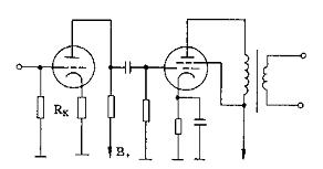
图8—23ä¸é˜´æžç”µé˜»RKä¸åŠ æ—路电容,音频信å·çš„å±æžç”µæµé€šè¿‡RK以åŽï¼Œä½¿RK两端由于é™åŽ‹ä½œç”¨äº§ç”Ÿäº†ä¸€ä¸ªéŸ³é¢‘ç”µåŽ‹ï¼Œè¿™ä¸ªç”µåŽ‹å’Œæ …æžä¸ŠåŽŸæ¥è¾“入电压相ä½æ˜¯ç›¸å的,所以产生了负å馈作用。
电æµè´Ÿåé¦ˆä¸€èˆ¬åŠ åœ¨åŠŸæ”¾æœºä¸çš„ä¸é—´æ”¾å¤§çº§æˆ–推动放大级。一般功率管阴æžæ–½åŠ 电æµè´Ÿå馈功率放大会é™ä½Žè¾“出功率和增大å±æžå†…阻。
图8—24是å¦ä¸€ç§æžé—´è´Ÿå馈电路。
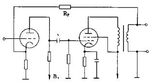
利用æžé—´è´Ÿå馈亦能有效地抑制噪声,图8—24ä¸çš„电压负å馈电阻RP是设置在ä¸é—´æ”¾å¤§çº§ä¸Žè¾“出级之间。
级间负å馈电阻与阴æžç”µé˜»ç›¸ä¸²è¿žï¼Œå‡¡è¢«åŠ è´Ÿå馈的ä¸é—´æ”¾å¤§çº§ï¼Œé™¤äº†å—å馈电阻RP作用外,一定还è¦æœ‰æœ¬çº§çš„电æµè´Ÿå馈。
级间负å馈ä¸é™å®šäºŒçº§ï¼Œäº¦å¯ä¸ºä¸‰çº§æˆ–四级,但必须注æ„其相ä½å…³ç³»ï¼Œå› 为负å馈电压的相ä½å¿…须和原æ¥è¾“入信å·ç›¸å·®180°。如相ä½ç›¸åŒï¼Œä¼šå½¢æˆæ£åé¦ˆè€Œäº§ç”Ÿè‡ªæ¿€ï¼Œç ´å放大器的æ£å¸¸å·¥ä½œã€‚
图8—25是整机负å馈电路。
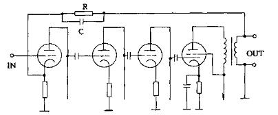
图8—25ä¸ä¸ºæ•´æœºè´Ÿå馈电路,RCè´Ÿå馈网络设置在输入级与输出级之间。这ç§æ•´æœºçš„è´Ÿå馈被称为大回环负å馈。
近年采由于这ç§æ·±åº¦çš„大回环负å馈,对功放的瞬æ€å“应ã€è½¬æ¢é€ŸçŽ‡ç‰æ€§èƒ½å¸¦æ¥å½±å“,故对整机负å馈é‡éƒ½åŠ 以åˆç†æŽ§åˆ¶ã€‚一般的å馈é‡æŽ§åˆ¶åœ¨6—12dB之间。
å››ã€ç”µåç®¡åŠŸæ”¾çš„é¢‘çŽ‡è¡¥å¿ éŸ³é¢‘åŠŸçŽ‡æ”¾å¤§å™¨çš„é¢‘çŽ‡å“应曲线,通常总是ä¸é¢‘段比较平å¦ï¼Œä½Žé¢‘段与高频段会显著下é™ã€‚与æ¤ç›¸å…³çš„相ä½ç‰¹æ€§ï¼Œè‹¥ä»¥ä¸é¢‘段的相ä½ä½œä¸ºåŸºå‡†ï¼Œåˆ™ä½Žé¢‘段的相ä½ç›¸å¯¹è¶…å‰ï¼Œè€Œé«˜é¢‘段的相ä½åˆ™ç›¸å¯¹æ»žåŽã€‚从ä¸é¢‘段到低频段和从ä¸é¢‘段到高频段的频率å“应曲线的下é™å’Œç›¸ä½å˜åŒ–,å„ç§åŠŸçŽ‡æ”¾å¤§å™¨å‡ä¸ç›¸åŒï¼Œä½†æœ€ä½Žé¢‘段与最高频段的频率å“应斜率和相ä½è§’的大å°ï¼Œæ€»æ˜¯å†³å®šäºŽè¯¥åŠŸæ”¾æœºçš„放大级数和电路形å¼ã€‚
在这ç§æƒ…况下补å¿çš„方法较多,但总的原则必须增大在相ä½å˜åŒ–为180度的频率时的增益é‡ä¸‹é™å€¼ï¼Œè€Œä¸”频率å“应的终端斜率ä¸å…许增大。
为了实现上述è¦æ±‚,应从声频范围的低频段与高频段,由频率å“应开始下é™çš„频率起到相ä½å˜åŒ–è¾¾180度的范围内进行频率特性补å¿ï¼Œä¸Žç›¸ä½çš„å˜åŒ–相比尽å¯èƒ½ä½¿å¢žç›Šé‡è¡°å‡å¤§äº›ã€‚一般æ¥è¯´ï¼Œä½¿è¿™èŒƒå›´çš„频率å“应的斜率ä¸å¤§äºŽ6分è´/å€é¢‘程,å³èƒ½è¾¾åˆ°ç›®çš„。
1 ä½Žé¢‘è¡¥å¿ ä¸€èˆ¬çš„é˜»å®¹è€¦åˆå¼æ”¾å¤§ç”µè·¯çš„低频段的频率å“应,最åŽå¯ä»¥ç”¨é€šç”¨ä½Žé¢‘è¡°å‡ç‰¹æ€§æ¥è¡¨ç¤ºã€‚
在多级放大器ä¸ï¼Œåº”采用阶梯法æ¥è¿›è¡Œè¡¥å¿ã€‚在这ç§æƒ…况下阶梯补å¿ç½‘络尽å¯èƒ½æŽ¥åœ¨å‰çº§æ”¾å¤§å™¨ä¸ã€‚如果将æ¤ç”µè·¯æŽ¥åœ¨é 近功放级时,则放大器低音频段的最大输出å³ä¼šå‡å°ï¼Œè‹¥è¦å‹‰å¼ºå¢žå¤§è¾“出,则阶梯网络之å‰çš„放大级ä¸å°†ä¼šäº§ç”Ÿæ˜¾è‘—çš„éžçº¿æ€§å¤±çœŸã€‚
图8—26是一ç§ä½Žé¢‘è¡¥å¿ç”µè·¯ã€‚
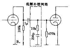
低音频段的阶梯补å¿ç½‘络的电å‚数,一般选择在低频段的频率å“应是从40HZ处开始下é™ï¼Œåˆ™é˜¶æ¢¯è¡¥å¿çš„高度约为12dB,在阻容耦åˆæ”¾å¤§ç”µè·¯ä¸çš„耦åˆç”µå®¹å™¨çš„容é‡å°½å¯èƒ½å¤§ä¸€äº›ã€‚
图8—27是低频补å¿ç‰¹æ€§æ›²çº¿å›¾ã€‚
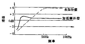
2 é«˜é¢‘è¡¥å¿ åœ¨é˜»å®¹è€¦åˆä¸Žå˜åŽ‹å™¨è¾“出的多级功率放大器ä¸ï¼Œé«˜é¢‘段的频率å“应也éšç€ç”µè·¯ä¸æ‚散电容的å˜åœ¨è€Œè¡°å‡ï¼Œæ•…必须进行补å¿ï¼Œæ‰èƒ½èŽ·å¾—高频段较平å¦çš„特性。
图8—28是一ç§é«˜é¢‘è¡¥å¿ç”µè·¯ã€‚
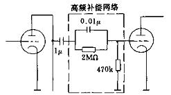
在多级放大器ä¸ï¼Œè¾“出å˜åŽ‹å™¨çš„高频特性是由自身决定的,故高频衰å‡çš„基准频率是固定ä¸å˜çš„。而阻容耦åˆæ”¾å¤§å™¨çš„基准频率则由耦åˆç”µå®¹ã€å±æžç”µé˜»ä¸Žç”µè·¯ä¸çš„æ‚散电容所决定。在实际电路ä¸ï¼Œä¸€èˆ¬é«˜é¢‘段的频率特性从10kHz以上å³å‘ˆè¡°å‡è¶‹åŠ¿ã€‚
è¿™æ ·é˜»å®¹è€¦åˆæ”¾å¤§å™¨çš„高频段在补å¿æ—¶çš„基准频率å¯ä»¥é€‰æ‹©åœ¨10kHz到50kHz之间。高频补å¿ç½‘络是由网络ä¸çš„电阻与电容所决定的,æ高基准频率的方法å¯å‡å°è¡¥å¿ç½‘络ä¸ç”µé˜»çš„阻值。
图8—29是高频补å¿ç‰¹æ€§æ›²çº¿å›¾ã€‚
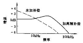
高频补å¿ç”µè·¯ä¸Žä½Žé¢‘è¡¥å¿ç”µè·¯åŽŸåˆ™ç›¸åŒï¼Œå…¶é˜¶æ¢¯è¡¥å¿ç½‘络应接入å‰çº§æ”¾å¤§å™¨ä¸ã€‚如将该补å¿ç½‘络接到末级ä¸ï¼Œåˆ™å®ƒçš„频率å“应开始下é™çš„频率移到音频范围之外,å¦åˆ™ä¼šå‡å°é«˜é¢‘的最大输出。
Our 12v battery pack designed to be chargeable via motorcycle/car cigaretter, capacity range from 2200mah to 10Ah, with wireless heat controller or bluetooth control. Applications widely ranges in heating clothing, heated motorcycle clothing, heated jacket, electric jacket, electric heated clothing, heated coat, heated vest, heated pants, heatgear, electric gloves, heated jacket mens, heated jacket womens.

12V Heated Jacket Battery
12V Heated Jacket Battery,Heated Jacket Battery, Heated Coat Battery,Heated Vest Battery
Asarke Industry Co., Limited , https://www.asarke-industry.com