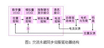
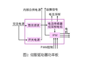
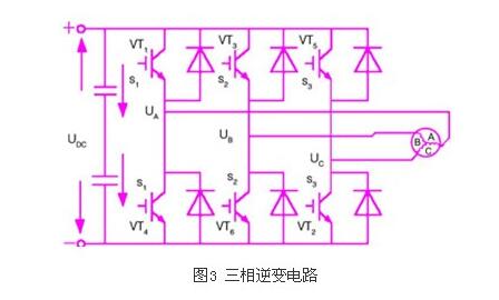
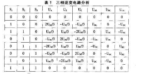
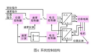
Modern AC servo systems have undergone a transition from analog to digital, digital control loops have become ubiquitous, such as commutation, current, speed, and position control; new power semiconductor devices, high-performance DSP plus FPGAs, and servo-specific modules ( For example, the servo-controlled special engine introduced by IR is not surprising. This article mainly introduces the principle and control method of modern AC servo system. AC permanent magnet synchronous servo driver mainly includes servo control unit, power drive unit, communication interface unit, servo motor and corresponding feedback detection device. Its structure and composition are shown in Figure 1. The servo control unit includes a position controller, a speed controller, a torque and current controller, and the like. Our AC permanent magnet synchronous drive integrates advanced control technology and control strategy, making it suitable for the servo drive field with high precision and high performance requirements. It also embodies powerful intelligent and flexible traditional drive systems. Unmatched. At present, the mainstream servo driver adopts a digital signal processor (dsp) as a control core, and its advantage is that a more complicated control algorithm can be realized, and the matters are digitized, networked, and intelligent. The power device generally adopts a driver circuit designed with an intelligent power module (ipm) as the core. The ipm integrates a driver circuit, and has a fault detection and protection circuit such as an over-voltage, over-current, over-heat, and under-voltage, and is also added to the main circuit. Start the circuit to reduce the impact of the startup process on the driver. The servo driver can be generally divided into two modules: a power board with a relatively independent function and a control board. As shown in Fig. 2, the power board (drive board) is a strong electric part, which includes two units. One is a power drive unit ipm for driving the motor, and the other is a switch power supply unit providing digital and analog power for the entire system. The control board is a weak part and is the control core of the motor and the carrier of the core control algorithm of the servo driver technology. The control board outputs the pwm signal through the corresponding algorithm as the driving signal of the driving circuit to change the output power of the inverter so as to achieve the purpose of controlling the three-phase permanent magnet synchronous AC servo motor. Power Drive Unit The power drive unit first rectifies the input three-phase power or mains power through a three-phase full-bridge rectifier circuit to obtain the corresponding direct current power. After rectifying a good three-phase power or mains power, a three-phase sinusoidal pwm voltage inverter is used to drive a three-phase permanent magnet synchronous AC servo motor. The entire process of the power drive unit can be simply referred to as the ac-dc-ac process. The main topology circuit of the ac-dc rectifier is a three-phase full-bridge uncontrolled rectifier circuit. The inverting part (dc-ac) adopts the power device set driving circuit, protection circuit and power switch integrated in the intelligent power module (ipm), the main topology is the schematic diagram of the three-phase inverter circuit shown in Figure 3, using The pulse width modulation technique pwm (pulse width modulaTIon) changes the frequency of the output waveform of the inverter by changing the time when the power transistor is alternately turned on, and changes the on-off time ratio of the transistor in each half cycle, that is, by changing the pulse width. To change the inverter output voltage of the secondary value in order to achieve the purpose of regulating power. In FIG. 3, vt1 to vt6 are six power switch tubes, and s1, s2, and s3 represent three bridge arms, respectively. The following provisions are made for the switching states of the bridge arms: When the upper bridge switch tube is in the "on" state (at this time the lower bridge arm switch tube must be in the "off state"), the switch state is 1; when the lower bridge arm switch tube is "opened" In the state (in this case, the lower arm switch must be in the OFF state), the switch state is 0. The three bridge arms have only two states of “0†and “1â€, so s1, s2, and s3 form a total of eight switching modes of 000, 001, 010, 011, 100, 101, and 111, among which the 000 and 111 switching modes make The inverter output voltage is zero, so this switch mode is called zero state. The output line voltage is uab, ubc, uca, the phase voltage is ua, ub, uc, among them udc is direct-flow power source voltage, according to above can obtain the analysis of the table. control unit The control unit is the core of the entire AC servo system and implements system position control, speed control, torque and current controllers. The digital signal processor (dsp) used in addition to fast data processing capabilities, also integrates a wealth of dedicated integrated circuits for motor control, such as a / d converter, pwm generator, timer counter circuit, asynchronous communication Circuits, can bus transceivers, and high-speed programmable static RAM and large-capacity program memory. The servo driver realizes the vector control (vc) by adopting the magnetic field oriented control principle (foc) and coordinate transformation, and at the same time, controls the motor in combination with the sine wave pulse width modulation (spwm) control mode. The vector control of the permanent magnet synchronous motor generally controls the stator current or voltage by detecting or estimating the position and amplitude of the rotor flux of the motor. Thus, the torque of the motor is only related to the magnetic flux and the current, similar to the control method of the DC motor. , can get very high control performance. For a permanent magnet synchronous motor, the rotor flux position is the same as the rotor mechanical position, so that the position of the rotor of the motor rotor can be known by detecting the actual position of the rotor, so that the vector control of the permanent magnet synchronous motor is comparable to the vector control of the asynchronous motor. Simplified. Servo Drive Control PM PM servo drive (PMSM) servo drive can work under current (torque), speed, and position control modes when controlling AC PM servo motor. The control block diagram of the system is shown in Figure 4. Because the PMSM servo motor (pmsm) uses permanent magnet excitation, its magnetic field can be regarded as constant; at the same time, the motor rotation speed of the permanent magnet servo motor is the synchronous rotation speed, that is, its rotation. The difference is zero. These conditions greatly reduce the complexity of the mathematical model of the AC servo drive in driving the AC permanent magnet servo motor. As can be seen from Figure 4, the system is based on measuring the two-phase current feedback (ia, ib) and motor position of the motor. The measured phase current (ia, ib) is combined with the position information, and the coordinates are changed (from the a, b, c coordinate system to the rotor d, q coordinate system) to obtain the id and iq components and enter the respective current regulators. . The output of the current regulator is changed by the inverse coordinate (converted from the d,q coordinate system to the a,b,c coordinate system) to obtain the three-phase voltage command. Through the three-phase voltage command, the control chip obtains six pwm wave outputs to the power device after the reverse and delay, and controls the motor operation. Under different instruction input modes, the system passes instructions and feedback through corresponding control regulators to obtain the next-level reference instruction. In the current loop, the d, q axis torque current component (iq) is the output of the speed control regulator or an external reference. In general, the magnetic flux component is zero (id=0), but when the speed is greater than the limit value, a higher speed value can be obtained by the weak magnetic field (id<<0). From the a, b, c coordinate system to d, the q coordinate system is implemented by the clarke and parker transforms; from the d, q coordinate system to the a, b, and c coordinate systems, there are Clarke and Parker. The inverse transformation is implemented. 1, torque control The torque control method is to set the external output torque of the motor shaft by the external analog input or the direct address assignment. 2, position control The position control mode generally determines the rotation speed by the frequency of the externally input pulse, and determines the rotation angle through the number of pulses, and some servos can directly assign the speed and the displacement through the communication mode. Because the position mode can have very strict control on speed and position, it is generally applied to a positioning device. 3, speed mode Through the analog input or pulse frequency can be controlled by the rotation speed, in the presence of the upper control device of the outer ring PID control speed mode can also be positioned, but must be the motor position signal or direct load position signal to the upper Feedback to do calculations. Modern AC servo systems were first applied to aerospace and military applications such as artillery and radar control. Gradually entered the industrial and civil areas. Industrial applications include high-precision CNC machine tools, robots, and other generalized CNC machines, such as textile machinery, printing machinery, packaging machinery, medical equipment, semiconductor equipment, postal machinery, metallurgical machinery, automated assembly lines, and various specialized equipment. The industries with the largest amount of servo usage are: machine tools, food packaging, textiles, electronic semiconductors, plastics, printing, and rubber machinery, totaling more than 75%.
Desktop style 12v and 24v series can be used in many different electronics. EMC, LVD, FCC, RoHS are available in our company. OEM and ODM are available, samples are free for testing, all our products have 2 years warranty.
Our products built with input/output overvoltage protection, input/output overcurrent protection, over temperature protection, over power protection and short circuit protection. You can send more details of this product, so that we can offer best service to you!
Led Adapter, Lcd Adapter,Speaker Power Adapter,Lcd Power Supply Shenzhen Waweis Technology Co., Ltd. , https://www.waweisasdapter.com