First, the principle and general requirements
The insulation resistance and electrical strength test clauses seem to be very simple, and most people in the industry think that the clause can be understood, but there are often many errors in the operation.
First, the difference between high-voltage breakdown in electrical strength and insulation resistance and leakage current should be distinguished. In the use of electrical appliances, the insulation layer will be impacted by high-voltage pulses generated by the inductive electrical disconnection, and will also be affected by the trigger pulse and lightning induced pulse. The electrical strength index is to assess the ability of the insulation layer to resist electrical breakdown. There are two cases of breakdown. One is that there is not enough electrical clearance, and space breakdown discharge occurs under high voltage. Such breakdown generally does not cause permanent insulation damage. Another type of breakdown is the breakdown of the dielectric medium. Since the dielectric medium is usually organic, when the organic substance is broken down by high voltage, the insulation at the breakdown point is carbonized by the high voltage discharge, thus causing permanent electrical insulation to be destroyed. The high voltage breakdown of lighting appliances is mostly the latter. In the IEC standard, the definition of electrical breakdown of a general electrical appliance is that under the action of high voltage, the current caused by the high voltage is ≥100 mA, and the electrical strength is not satisfactory, and the electrical appliance is generally unrecoverable after electrical breakdown. It is a direct threat to personal safety. The insulation resistance and leakage current are the leakage currents generated by the insulation under a certain voltage. This leakage current does not invalidate the insulation. When this leakage current is large (about 0.5 mA to 5 mA depending on the sensitivity of the person's electric power), it will give people a feeling of electricity, and this leakage current will not directly harm the healthy person. However, if you are instinctively dodging when you are working at heights, you may cause high altitude fall damage. In addition, certain heart disease people may have obvious harm, so restrictions are imposed. Most of them use a megohmmeter to measure the insulation resistance to limit the leakage current of the control device and some parts of the lamp. However, it is required to disconnect the capacitance and inductance that affect the measurement result when measuring the insulation resistance (see GB7000.1 standard 10.2). The leakage current meter with weighted network is used to measure the leakage current of the whole luminaire. The measurement result of the leakage current of the whole luminaire includes not only the leakage current generated by the insulator under the voltage, but also the capacitance of the luminaire. Leakage current should be generated (see GB7000.1 Standard 10.3).
After understanding the above-mentioned electrical strength test connotation, we should also pay attention to the IEC standard requirements for the electrical strength of lighting appliances. The operating voltage referred to in the standard means the maximum steady-state rms voltage (excluding the transient value) generated between the terminals or the terminals to the ground during operation of the lighting appliance, including normal and abnormal conditions. Due to the development of the lighting industry, there are many sources of light source control devices that are inspected according to the above requirements in the working state or in the abnormal state. The working voltage may exceed the input voltage (the light source is also required to be marked in the marking project). Control device operating voltage value). Therefore, in the electrical strength test, U in the test voltage 2U + 1000V of each light source control device should be calculated according to the nominal operating voltage.
Second, the electrical strength test requirements of lamps using LED light source
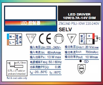
Figure 1 LED control device logo
The electrical strength test of luminaires using LED light sources is mostly more complicated than that of general luminaires. According to the different control devices used in the luminaires and the classification of anti-electric shock protection of lamps, they can be basically divided into the following cases:
1. Lamps with output as safety extra low voltage (SELV) or isolated control device
When conducting insulation resistance and electrical strength tests, first pay attention to the signs of the LED control device.
The output of the control device shown in Figure 1 is isolated safety extra low voltage (SELV), so the internal input and output must also be isolated.
For lamps using such LED control devices, the following tests shall be carried out in accordance with the requirements of Table 10.1 and Table 10.2 of Chapter 10 of GB 7000.1.
Figure 2 is a schematic diagram of each of the typical electrodes of a Class I lamp using an LED light source.
(1) Since the output terminal is SELV, the insulation resistance of the output terminal to the mounting surface and the metal casing of the lamp (in most cases, the two potentials are connected together) should be ≥1MΩ, and the voltage applied by the electrical strength is 500V/1min. breakdown.
The test between the different polarities on the output side can only be carried out after the control device and the LED module wiring on the terminal B are removed, and the insulation resistance should also be ≥1MΩ. The voltage applied by the electrical strength test was also 500V/1min.
(2) Because the input terminal is non-SELV and is of type I structure, the input end should be evaluated according to the basic insulation for the mounting surface and the metal casing of the lamp (in most cases, the same potential), that is, the insulation resistance should be ≥ 2MΩ, electrical strength The applied voltage should be (2Uin + 1000V) / 1min.
If the switch S of the power supply is present in the luminaire, the insulation resistance and electrical strength test of the live parts with different polarities shall be performed on L and N with the switch in the off position. The power cord and control unit line on terminal A should also be removed, and the insulation resistance and electrical strength test of live parts with different polarities should be performed on terminal A. Since the latter two cases require only basic insulation to meet the requirements, the test limits and voltages are the same as in the first case of this article.

Figure 2 Schematic diagram of each electrode of a class I lamp using an LED light source
(3) As can be seen from Figure 2, there are two possible channels for the input terminal electrode to the accessible conductive part:
a) person - lamp housing (grounding) - (basic insulation) - input power terminal and related lines
b) person - output terminal - LED control device (double or reinforced insulation) - input power terminal and related lines
Note: Because when the output voltage is SELV and the load voltage is ≤25V, the output can be exposed and accessible.