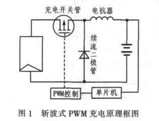
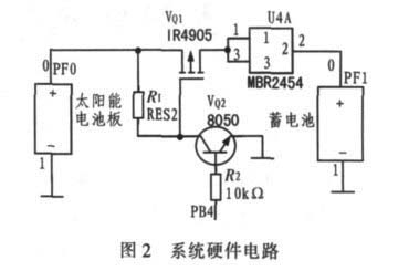
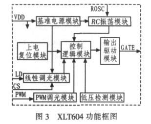
Abstract: In order to actively respond to the national energy conservation and emission reduction, vigorously develop and utilize new energy, for the purpose of practical application, a solar LED street lighting system was designed around solar photovoltaic technology and LED lighting technology. The selection principle of solar cell power and the matching method with battery capacity are introduced. The solar controller and LED driver in the solar lighting system based on ATmega128 MCU and XLT604 driver are analyzed. At the same time, the power selection and combination of LED in the chip are selected. I have analyzed the issues. The designed solar LED street lighting system has good illumination, environmental protection and energy saving, and meets the requirements of urban road lighting in Taiyuan. In recent years, with the development of solar photovoltaic technology and LED lighting technology, solar LED street lamps have entered the field of urban lighting. LED as an illumination source has DC low voltage drive, low power consumption, anti-vibration, long life, nanosecond response speed, large design space, environmental protection, continuous switching flash, and can be easily realized compared with traditional illumination sources. The advantages of 0 to 100% dimming function are considered to be a new generation of green lighting equipment. Solar LED street lights use solar energy as an energy source. Each street lamp is independent, easy to install, no need to lay cables and wires, no need to exchange electric energy and electricity, DC power supply, light control timing control, safe and reliable, energy saving, economical, environmental protection, practical. 1 Selection of solar panels and batteries 1.1 Solar panel selection At present, the photoelectric conversion efficiency of monocrystalline silicon solar cells is about 15%, and the highest is 24%. Currently, all kinds of solar cells have the highest photoelectric conversion efficiency and the most mature technology. The service life is generally up to 15 a and up to 25 a. The photoelectric conversion efficiency of polycrystalline silicon solar cells is much lower than that of monocrystalline silicon solar cells. The photoelectric conversion efficiency is about 12%, and the service life of polycrystalline silicon solar cells is also shorter than that of monocrystalline silicon solar cells. The photoelectric conversion efficiency of amorphous silicon thin film solar cells is low. At present, the international advanced level is about 10%, and it is not stable enough. As time goes by, its conversion efficiency is attenuated, which directly affects its practical application. Therefore, monocrystalline silicon solar cells are currently used. According to the principle of solar radiation, the amount of radiation obtained on the solar array is related to many factors: local latitude, altitude, atmospheric pollution or transparency, changes in the four seasons of the year, changes in the day, reaching the ground. The solar radiation value, the proportion of the scattered component, the reflection coefficient of the ground surface, the operation mode of the solar cell array or the inclination of the fixed square matrix, and the cleanliness of the surface of the solar cell array. The charging and discharging efficiency of the solar lighting system is 0.75, the loss correction coefficient of the solar battery module group is 0.95, and the dust shielding and other loss correction coefficient is 0.90. After the query data and unit conversion and simplified processing, the formula for calculating the total solar cell usage P can be obtained: Where Q L is the daily power consumption of the load (Wh); H L is the annual average daily radiation of the horizontal plane (KJ / (m 2 ·d)); K op is the optimum radiation coefficient of the inclined surface radiation; A is the safety factor, generally Take 1.1 to 1.3. 1.2 Selection of battery The capacity of the battery should be determined according to the power of the solar panel and the power of the LED street lamp and the lighting time. The battery should match the solar cell and the LED street lamp. A simple way to determine the relationship between them. The solar cell power must be more than 4 times higher than the load power for the system to work properly. The voltage of the solar cell should exceed 20% to 30% of the operating voltage of the battery to ensure normal storage of the battery. Therefore, the battery capacity must be more than 6 times higher than the daily load of the load. The formula for calculating the capacity Bc of the battery: Where PL is the daily average power consumption, D is the number of rainy days, Kb is the safety factor, 1.1 to 1.4 (including the temperature correction factor To = 0 °C is 1, and -10 °C is 1.1, -10 °C is 1.2, depth of discharge cc = 0.75), V is the operating voltage. According to formula (2), the capacity of the battery can be estimated, and the charging efficiency of the battery depends on the way of charging. According to the system requirements and the verification of various indicators, the 12 V 100 Ah valve-regulated sealed lead-acid battery is used here. 2 solar controller hardware design The solar controller is called the solar charge and discharge controller. It is an automatic control device that controls the solar cell array to charge the battery and the battery to supply the load. It can automatically prevent the battery from overcharging and overdischarging. It regulates and controls the charging and discharging conditions of the battery, and controls the power output of the solar cell module and the battery to the load according to the power demand of the load, which is the core control part of the whole system. The charging controller designed in this paper uses ATmega128 single-chip microcomputer as the main control device to detect the output voltage of the solar panel, select the appropriate DC/DC branch, detect the voltage value of the battery, and select the appropriate charging method according to the charge state of the battery. Provide overcharge and overdischarge protection. Figure 1 shows the chopper-type PWM charging schematic diagram, detecting the charging terminal voltage of the battery, and comparing the detected battery terminal voltage with a given point voltage. If the voltage of the battery is less than a given voltage, the chopper is fully connected to quickly charge the battery; if it is greater than the given voltage, the duty cycle of the power tube is adjusted according to the ratio, the charging enters the slow charging phase, the charging characteristics are improved, and finally, the charging is performed. Stream charging to prevent overcharging. The AVR128 single-chip microcomputer (PB4) gives the charging control signal, that is, PB4=1, the NPN type 0805 transistor is turned on. At this time, the collector is grounded, so that the IRF4905 gate-source voltage is clamped at -10 V, and the IRF4905 tube is turned on. The board charges the battery; on the contrary, the NPN type 0805 transistor cuts off VGS=0 V, the IRF4905 tube is disconnected, and the solar panel cannot charge the battery. The ATmega128 has a 10-bit successive approximation A/D converter. The A/D converter is connected to an 8-channel analog multiplexer, sampling eight single-ended input voltages at port F. The positive pole of the battery is connected to the PF1 pin of the MCU. When the voltage is as low as 10 V, the MCU automatically detects and processes it accordingly, as shown in Figure 2. 3 LED selection LEDs are classified according to the input power of current market products, where the input power is several tens of mW, which is called a traditional low-power chip; the input power is less than 1 W, which is a power LED; the input power is equal to 1 W or greater than 1 W. , is a W-class power (high power) LED. At present, the high power is more common, 1, 3, 5, 8, 10 W. 1 W and 3 W LEDs have been applied in batches and are moving toward high current (300 mA to 1.4 A), high efficiency (60 to 1 204 lm/W), and adjustable brightness [3]. High-power LED street lights use a single LED with a power greater than 1 W. The 3 W LED of American CREE Company is used to integrate multiple chips into a dot matrix array with a certain pitch as a planar light source on the printed circuit board, and combined into a high-power LED single module, which is incorporated into the street lamp fixture, thereby improving the chip. Area and increase the amount of luminescence. Combining multiple LEDs to design road lighting, in addition to sufficient luminous flux and reasonable optical design to ensure a reasonable light distribution, more important is the heat dissipation problem. Because the street lamp has outdoor nighttime use, the heat dissipation surface is located on the side and the body shape is limited, which is beneficial to the natural convection heat dissipation of the air. Therefore, the LED street lamp selects the natural convection heat dissipation mode, and the whole lamp adopts the high thermal conductivity aluminum as the heat dissipation body to solve the problem. The heat dissipation problem of the LED. 4 LED combination and driving method There are three common combinations of LEDs: parallel, series, and hybrid. 1) Parallel mode requires the LED driver to output a large current and the load voltage is low. The voltages distributed across all LEDs are the same. When the LEDs have a large difference in consistency, the current through each LED is inconsistent and the brightness is different. 2) The series mode requires the LED driver to output a higher voltage. When the consistency of the LEDs is large, the voltages distributed across the different LEDs are different. The current through each LED is the same, and the basic brightness of the LEDs is the same. 3) Hybrid mode When more LEDs are needed, if all LEDs are connected in series, the LED driver will need to output a higher voltage; if all LEDs are connected in parallel, the LED driver will need to output a large current. Connecting all or three LEDs in parallel not only limits the amount of LEDs used, but also increases the load current of the parallel LEDs and increases the cost of the drivers. The number of LEDs in the hybrid mode is evenly distributed, and the voltages distributed on one string of LEDs are the same. The currents on each LED through the same string are also basically the same, and the brightness of the LEDs is the same. At the same time, the current through each string of LEDs is also similar. Through the above analysis, high-power LEDs are used in the field of illumination. Since the current and voltage parameters of LEDs have typical PN junction volt-ampere characteristics, small changes in forward voltage drop cause large forward current changes. Unstable operating currents can affect LED life and light decay. Therefore, the brightness of the high-power LED is completely controlled by the current, and the drive circuit must provide a constant current. The high-power LED driver XLT604 is used to drive the LEDs in the driver circuit. The XLT604 is a PWM high efficiency LED driver controller designed in BICMOS technology that effectively drives high brightness LEDs from an input voltage range of 7 to 450 VDC. The driver can drive an external MOSFET at a fixed frequency up to 300 kHz, the frequency of which can be programmed by an external resistor. The external high-brightness LED string can be controlled by constant current to maintain constant brightness and enhance the reliability of the LED. The constant current value is determined by the external sampling resistor value, ranging from a few mA to 1 A. The XLT604-driven LED can adjust the brightness linearly through the external control voltage, and the brightness of the LED string can be adjusted by the external low-frequency PWM. Therefore, according to the actual needs of the solar LED street lamp design, the LED hybrid mode is selected, and the XLT604 driver is used to design the drive circuit to drive. LED, as shown in Figure 3. The main functions of each pin of XLT604 are: LD is linear input dimming terminal; ROSC is oscillating resistor access segment; CS is LED current sampling input terminal; GND is chip ground; GATE is driving external MOSFET gate; VDD is chip power supply; PWM is the PWM input dimming terminal and doubles as the enable terminal. 5 Solar 30 W LED Street Light System Design The total annual sunshine hours in Taiyuan is 2 360 to 2 796 h. The annual total solar radiation is 5 442.8~5652.18 MJ/m 2 , and the peak sunshine hours are 4.832 053 2, which belongs to the national high illumination rate. Therefore, the Taiyuan area has good solar energy utilization conditions. The following is an example of the 30 W LED street light system in Taiyuan: 1) Determine local meteorological and geographical conditions. Data are inquired about Taiyuan area: latitude: north latitude 37°27′~38°25′, longitude: east longitude 111°30′~113°09′ altitude: 800 m, longest rainy day: 7 d    2) Determination of daily load consumption The lighting street lamp power is 30 W, and the continuous working time is 10 h per day. Therefore, the daily power consumption is: QL=30 w×10 h=300 Wh (3)    3) Determination of the inclination angle The inclination angle of the Taiyuan area is 38°, and the optimal inclination angle of the solar panel is 38°+5°=43°. Therefore, the solar panel faces the south. 4) Calculation of total energy of solar cells Through data query, we know that Kop=1.1 in Taiyuan area, data from local latitude, longitude, altitude, and local meteorological department: The daily average solar radiation in Taiyuan is 15 MJ/(m) 2 · d), therefore the annual average daily radiation amount of the horizontal plane is HL = 15 000 KJ / (m 2 · d). Solar cell selection component parameters: operating voltage is 17.2 V, operating current is 3.49 A, open circuit voltage is 21.6 V, short circuit current is 3.9 A, peak power is 60 Wp. A solar panel with a peak power of 60 Wp is used, and two solar modules are used, and the solar battery is designed to charge 12 V batteries. 5) Calculation of battery capacity Bc    The capacity Bc of the battery can be calculated by using equation (5): Therefore, two sets of 12 V 100 Ah valve-regulated sealed lead-acid batteries can be selected. At present, high-power LED street lamps are basically white light with a color temperature of about 5 000 K. As a road illumination source, the visual sense is too cold, and the observation ability will decrease when it is farsighted. The warm white light of about 3 000 K is suitable for road lighting. At the same time, the wind-proof design of the battery pack bracket and the wind-resistant design of the pole are also considered. The working voltage of the LED street lamp is generally 12 V or 24 V, which is a safe voltage and does not make electrical protection ground. However, the LED street light metal pole should be grounded and the grounding resistance is not more than 10 Ω. 6 Conclusion The solar LED street lighting system is the perfect combination of natural energy solar energy and environmentally friendly light source LED, and its development prospect is extremely broad. However, there are still many problems in the practical application of solar LED street lamps. Including: 1) centralized management issues; 2) solar cell life, battery life and other control component life is often lower than LED life; 3) the height of the solar cell with a relatively high installation height brings the design of the pole The problem of improving wind resistance. These problems are all needed to further solve the problem of solar LED street lighting.
If you are fed up with carrying around heavy
and clunky speakers, then this Portable Bluetooth Speaker is ideal for
you. Featuring a compact and sleek design that you`ll want to show off, it will be any youngster`s
instant favorite!We are a professional Chinese manufacturer of Portable Bluetooth Speaker , and look forward to your cooperation!
Portable Bluetooth Speaker Portable Bluetooth Speaker,Portable Wireless Bluetooth Speaker,Bluetooth Portable Speaker,Mini Portable Bluetooth Speaker Reteck Storage Device Co., Ltd. , http://www.reteck.com


3 times
Window._bd_share_config = { "common": { "bdSnsKey": {}, "bdText": "", "bdMini": "2", "bdMiniList": false, "bdPic": "", "bdStyle": " 0", "bdSize": "24" }, "share": {}, "image": { "viewList": ["qzone", "tsina", "tqq", "renren", "weixin"], "viewText": "Share to:", "viewSize": "16" }, "selectShare": { "bdContainerClass": null, "bdSelectMiniList": ["qzone", "tsina", "tqq", "renren" , "weixin"] } }; with (document) 0[(getElementsByTagName('head')[0] || body).appendChild(createElement('script')).src = 'http://bdimg.share. Baidu.com/static/api/js/share.js?v=89860593.js?cdnversion=' + ~(-new Date() / 36e5)];