China Construction Electronic Engineering Co., Ltd.
Abstract: This paper briefly describes the limitations of the traditional bus system, and elaborates the network infrastructure platform of IPV6 intelligent lighting control platform, IPV6 intelligent lighting control and management platform structure and the main working part area management system, from the regional scene control work process, power metering The management collection process and the alarm information collection process describe the work process in three aspects, which leads to the combination of distributed control and centralized management. The intelligent control platform is the biggest feature of the Olympic Central District lighting control system.
Keywords : lighting control unit, metering management unit, area unit, management unit
1. introduction
We all know that the loss of time does not make some good things disappear, but unfortunately something that we seem to be good does not mean that it can be used forever, no matter how brilliant it is now, it will be outdated. Or it will be developed, there will always be fresh things to cover its original light, just like the Olympic record has been refreshed again and again, giving people a new surprise, new excitement. In response to the theme of the Olympic Games and the Green Olympics, the lighting system in the Olympic Center has adopted an IPV6 address network platform with a large address space and a faster routing speed, and a control system combining distributed control and centralized management, which also added to the Olympics. A glory.
Traditional bus-type lighting control systems have developed for a long time and are widely used. However, in the face of large-scale lighting such as the central park of the Olympic Park, traditional bus-type lighting has exposed certain limitations:
1. The address space of the bus type lighting control system is limited, such as RS485, which can connect up to 31 terminals;
2. The lighting requirements of the central area of ​​the Olympic Park require different lighting scenes according to the usual time, holidays, large-scale competitions and different time periods of the day. The bus-type lighting control system lacks flexible scene customization capabilities;
3. The bus type lighting control system mainly adopts RS485 for physical layer transmission, and the transmission rate of control signaling is relatively low, which easily becomes the bottleneck of the system;
4. Due to incomplete information of field-level equipment, online fault diagnosis, alarm, and recording functions are not strong. Bus-type lighting control systems pay more attention to the control of lighting equipment, and the processing power in operational analysis is relatively weak and cannot be given. Accurate operational optimization recommendations.
It can be seen that in order to meet the requirements of lighting control and management in the central area of ​​the Olympic Park, it is necessary to realize the IPization of the lighting control loop, make full use of the network technology, improve the control and management level, effectively improve the operational analysis capability, and save operating costs.
2.2 IPV6 basic network platform
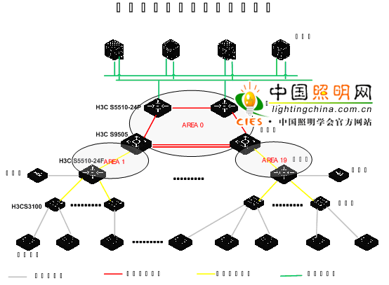
Taking into account the technical standards required by the equipment in the network and the special requirements of the Olympic project, the domestic Huawei 3com network product network platform was selected, and the IPV6 address method was adopted to meet the development needs of the Olympic venue network application. The specific network topology is as follows:

Network topology description:
1. The entire network uses OSPF as the routing protocol, including two server access switches and two core switches. It serves as the core area of ​​the OSPFv3 Backbone area, that is, AREA 0. The server that accesses the core area implements centralized management through a software platform that integrates control, maintenance, and management.
2. The aggregation layer device uses 19 5510 switch devices. The aggregation layer device and the core layer device are both connected to each other. Put the two links into the common area of ​​OSPFv3. The area IDs are AREA 1 to AREA 19.
3. The access layer device is 119 3110 Layer 2 switches. The access layer device and the aggregation layer device are all TRUNK links. There is no Layer 3 connection, and they can access each other through the management address of the switch. All access layer equipment is placed in a special distribution box and combined with Matsushita Electric's lighting terminal control equipment (area management system) to implement distributed control functions.