High-end smartphones and their supply ecosystems show the fact that consumers need mobile broadband and applications that can help them closely link information, family and friends. Therefore, mobile broadband has become the most significant part of the growth of the telecommunications industry today. Even if economic growth slows, telecom operators' revenues in wireless data have increased significantly in recent years. The rapid growth of Netbook and HSDPA-USB interface devices also shows that consumers need broadband anywhere, not just in their homes and offices. This article refers to the address: http:// Figure 1a Traditional base station Figure 1b Distributed base station Figure 1c Distributed base station topology Figure 2 Distributed base station architecture signal flow Figure 3a CPRI communication protocol layer stack Figure 3b CPRI communication protocol layer stack (external SerDes division) Figure 4 2G/3G/4G REC connected to 3 REs Conclusion When network equipment manufacturers build 4G infrastructure, the need for high-sequence data rates between radio control and radios in distributed base station architecture deployments will increase dramatically. To meet this need, SerDeson at both ends of the fiber optic cable must perform at a higher level. Network equipment manufacturers can cut the system and use the same familiar FPGA platform for logical layer processing. To achieve high sequential data rates, network equipment manufacturers can use the discrete SerDes solution to upgrade the SerDes portion separately. This segmentation achieves the required performance without the learning cycles required by the new FPGA platform, and helps to increase economies of scale and ultimately reduce the cost of the manufacturer. LiFePO4 Energy Storage Cell features high power density, long cycle life, deep depth of discharge, low self-discharge, and thermal stability. We manufacture LFP Lithium Battery cells of a great variety of sizes and capacities, which can be made into battery packs of different shapes and power. LiFePO4 Energy Storage Cell Lfp Battery,Electric Vehicle Battery,Traction Battery FORZATEC CO., LIMITED , http://www.forzatec.com
When consumers use mobile devices to access data, they still feel inconvenienced because the download speed is too slow and the graphics display is not good. Applications such as video blogs and online games require faster connection speeds and shorter delays. Faster and more stable connections facilitate the development of cloud computing-related applications, and mobile office applications will not be limited by hardware processing capabilities.
Of the 4.3 billion wireless network users, about 80% are GSM users who simply use voice. Therefore, mobile system providers are very optimistic about the growth opportunities of 3 billion users in the next 5 to 10 years to bid for mobile broadband. Devices such as IPTV and digital cameras that have mobile broadband connectivity and enable new services may also have such growth, thereby increasing the revenue of mobile operators.
In response to increasing demand and faster and more stable connections and shorter latency, global network operators want to be able to build 4G networks, and LTE is the first in the world.
• The LTE specification provides a maximum downlink (downlink) rate of over 100 Mbps with an uplink (reverse transmission) of over 50 Mbps and a Radio Access Network (RAN) with round-trip delays of less than 10 ms.
â— LTE also uses advanced antenna technology concepts such as beam forming to expand coverage. High peak data rates can be achieved with multilayer antenna solutions, such as 2x2 or 4x4 multiple input and multiple output (MIMO).
Despite the emergence of new standards with all the best features, wireless and mobile network operators must continue to face the challenges of investment costs and network deployment to meet future surges in bandwidth demand. Network operators must choose the most cost-effective network evolution for 4G. To deploy a 4G-standard network such as LTE, the required network upgrades must not only balance the limited availability of the new range, but must also be applied to existing areas. In order to effectively manage increasingly complex standards, the concept of Distributed Open Base Station Architecture has emerged with these standards to provide a low-cost, flexible modular environment to manage radio access evolution.
The conventional base station deployment shown in Figure 1a requires the radio controller (REC) and radio (RE) together with the antenna tower to be placed in a single chassis. Such an approach would cause network operators to face unfavorable factors such as increased size, increased power consumption, and increased cost in actual settings. This type of architecture also causes signal loss in the cable connecting the antenna to the RE. 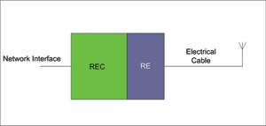
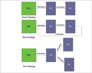
The Distributed Base Station Architecture (DBSA) shown in Figures 1b through 1c allows the rest of the base station to be completely devoid of RF transceivers. This architecture enables the RE to be located closer to the individual antennas in order to minimize the power loss between the RE and the antenna in Figure 1b, thereby reducing the cost of amplifying the RF power. The DBSA also allows for a variety of different RE network topologies, such as the chain, ring or tree as shown in Figure 1c. Such an approach can indeed scale down the network setup because the radios can be connected to each other without the need for each RE to communicate with a single REC. 
The Open Base Station Architecture Founding Alliance (OBSAI) and Common Public Radio Interface (CPRI) standards apply to baseband data communications between radio controllers and radios, as well as radio equipment networks in DBSA. After standardizing the interface between the REC and the RE, the REC and RE devices of different vendors can be used interactively. At the same time, 2G/3G/4G RECs can communicate with different REs, thus enabling multiple standards of integration and simultaneous operation, and reducing the need for equipment upgrades.
Both CPRI and OBSAI specify a high-speed serial interface between their radio controllers and radios to achieve baseband data transmission (I/Q data) and command/control and synchronization on the same interface (for RE networks) ) Communication of information.
Figure 2 shows the signal flow in the DBSA. For a foward link RE, the OBSAI/CPRI data is restored by the Sequencer/Deserializer (SerDes), which converts the high speed sequence data into parallel data and then transfers this data to the FPGA. The FPGA processes the OBSAI/CPRI logic and then transmits the I/Q baseband samples to a digital boost converter (dedicated logic) to adjust the I/Q baseband samples to the digital IF carrier. The upconverted data is then processed by the data processing engine to reduce the crest factor (dedicated logic) and digitally predistort the signal (dedicated logic) to compensate for the side lobe generated in the power amplifier, And ensure that the power amplifier can operate in a linear region. 
In the uplink, the radio frequency module contains all the analog functions, which can downconvert the RF band to the intermediate frequency and then digitally downconvert the individual carriers to the sampled fundamental in-phase and quadrature (I/Q) groups. . Multi-tasking baseband sampling (I/Q) and control and management data in downstream and backhaul are serialized and then transmitted over fiber optic cables via SerDes devices (eg, TLK3134 from Texas Instruments) .
If you want to analyze the 4G evolution of DBS and the required glitch to achieve faster and more stable data connection, it will cause another important issue. As the data rates of the downlink and uplink increase, and more and more network sponsored users switch to high-bandwidth applications such as on-demand TV, the sequence data rate between REC and R increases. The sequence data rate (SDR) between REC and RE can be calculated using equation (1):
SDR=MAcSN2(I/Q)C (1)
Where SDR is the sequence data rate between REC and RE; M is the number of antennas; Ac is the number of carriers/antennas; S is the sampling rate (the number of samples per second per sample); N is the sampling width, bits/sampling; C is 8b10b data during serial transmission between REC and RE (10/8 = 1.25); 2 (I/Q) = 2 times multiplication factor of in-phase and quadrature phase data.
Through Equation 1 and Table 1, for four W-CDMA carrier and dual antenna systems, the sampling rate is 7.68 million samples per second for each carrier, and the 20 MHz radio frequency with IQ sampling width of 4b/sample is original. The sequence rate is shown in Equation 2:
SDR=2×4×7.68×4×2×1.25= 614.4Mbps (2)
Similarly, through Equation 1 and Table 1, for a four-antenna system, a single carrier/antenna, the LTE carrier sampling rate is 30.72 million samples per second for each carrier, and the 20 MHz radio frequency with an IQ data sampling width of 16b/sample is The original sequence rate is as shown in Equation 3:
SDR=4×1×30.72×16×2×1.25=4.915Gbps (3) 
For an eight-antenna beamforming LTE system, the SDR in Equation 3 is multiplied to 9.8 Gbps. Therefore, an increase in the IQ sample width, channel width, or number of antenna carriers directly results in an increase in the sequence data rate between the REC and the RE. Network equipment manufacturers building infrastructure should understand that in LTE evolution, the sequence data rate must be adjusted from a medium rate of 614.4 Mbps to 9.8 Gbps or 12.2 Gbps. DBSA's high SDR requires SerDes at both ends of the fiber optic cable to perform at a higher performance to achieve stable frequency data recovery and meet the jitter specifications of the CPRI or OBSAI standards. To further understand the 4G SerDes and data processing utilities, the following will analyze the CPRI/OBSAI communication protocol stack.
Figure 3a shows the CPRI communication protocol layer stack. In general, the physical layer contains fixed functions that are common to different communication protocols. The fixed-function physical layer of the CPRI/OBSAI communication protocol layer is implemented in a hardware macro (hard marco) approach to meet stringent timing closure requirements. However, the logic layer allows customization. As the emerging standards evolve and network equipment manufacturers expect to add value through proprietary features, the logic layer will be updated. When implementing the logic layer portion of the CPRI/OBSAI interface, the FPGA typically provides the resiliency required. FPGA logic projects can be designed with programs to support custom logic layers. 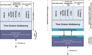
As network equipment manufacturers switch to 4G deployments, they need not only the same flexibility to implement the logic layer, but also the need to enhance SerDes performance to meet the increased SDR. Network equipment manufacturers can choose to purchase FPGAs with integrated SerDes, or choose to purchase FPGAs and discrete SerDes, and then combine the two (see Figure 3b).
Here are a few key factors you must consider when choosing a discrete SerDes-FPGA and an integrated SerDes-FPGA:
â— Cost of discrete SerDes plus FPGA vs FPGA cost of integrated SerDes
â— Performance of discrete SerDes vs. SerDes performance integrated in FPGA
â— Familiarity with a specific FPGA platform
â— Space saved by using integrated SerDes-FPGA
Figure 4 shows a 2G/3G/4G base station or REC connected to 3 REs serving 3 blocks respectively. Among them, the three CPRI settings are 614.4 Mbps, 3 Gbps, and 9.8 Gbps line rate, and 9.8 Gbps is assumed to be an updated SDR, which can support 4G. 
Condition A: Assume that network equipment manufacturers use FPGAs and discrete SerDes, and have invested time and resources in the learning cycle of that particular FPGA platform. To support 9.8Gbps in this situation:
â— Manufacturers upgrade SerDes and continue to use the same familiar FPGA platform. Advantages: Achieve economies of scale, as the three RE blocks shown in Figure 4 can all have similar FPGAs and operate with different SDRs. As a result, manufacturers do not need to change the FPGA platform to experience the learning cycle.
Condition B: Network equipment manufacturers use economical low-end FPGAs that have integrated SerDes capabilities. To support 9.8Gbps in this situation, manufacturers have three options:
â— Switch to 9.8Gbps high-end FPGAs from different manufacturers (with integrated SerDes). Disadvantages: Cost increases, and manufacturers must go through the learning cycle of the new FPGA platform.
â— Switch to a low-cost 9.8Gbps FPGA from the same manufacturer (with integrated SerDes). Disadvantages: performance doubts.
â— Purchase a SerDes-free FPGA from the same vendor and cut the system into an FPGA and discrete SerDes. Advantages: Manufacturers can save money by switching to FPGAs without SerDes while preserving the familiar FPGA platform. In addition, the same FPGA can be used to cut out three RE blocks using discrete SerDes to achieve economies of scale, as shown in Figure 4. Disadvantages: Discrete SerDes plus FPGA solutions may require more PCB space.
Condition C: Network equipment manufacturers use high-end FPGAs that have integrated with SerDes. To support 9.8Gbps in this situation, manufacturers have three options:
â— Switch to the same manufacturer's 9.8Gbps FPGA (with integrated SerDes). Disadvantages: Manufacturers may have to pay a very high cost for FPGAs with 9.8Gbps SerDes functionality.
â— Switch to 9.8Gbps low-order FPGAs from different manufacturers (with integrated SerDes). Disadvantages: learning cycle, performance doubts, lack of economies of scale to reduce costs.
â— Purchase a SerDes-free FPGA from the same vendor and cut the system into an FPGA and discrete SerDes. Advantage: Similar to Condition B.
In the case of high-speed SDRs such as 9.8 Gbps or 12 Gbps, it is not easy to meet the requirements for stable frequency data recovery, jitter tolerance, signal conditioning and signal integrity in discrete SerDes designs, not to mention integrated SerDes- In FPGA design, the noise isolation of sensitive analog circuits within the digital logic project block (most of the chip) creates greater design challenges. Sometimes, to achieve the required performance, FPGAs that have integrated SerDes require costly power supply filtering and choose to use a voltage controlled crystal oscillator or a lower cost crystal oscillator. These requirements increase the cost of implementation. In summary, integrating SerDes into FPGAs can create associated costs, and these costs increase as integration difficulties increase due to increased SDR. This is one of the main reasons why FPGA plus discrete SerDes solutions are more cost effective than integrated solutions when data rates are at 3 Gbps or lower.