The circuit is mainly composed of a high frequency oscillation circuit, a triple voltage rectifier circuit and a high voltage power grid.
AC Input : 100V to 240V, DC Output: 12 volt at 2 amp rating . Please refer to the ASIN :B0746GCGQ8 if u need 10 units.
COMPACT DESIGN and LOW CONSUMPTION makes it ideal for taking around and using at home.
12v wall charger,12v switching adapter,(12V/2A) Switching Mode Power Adapter Wall Charger,12V 2A Power Supply Adapter,12 Volt 2 Amp Power Adapter,12V 3A Power Supply Adapter,12v3a wall charger Shenzhen Waweis Technology Co., Ltd. , https://www.waweis.com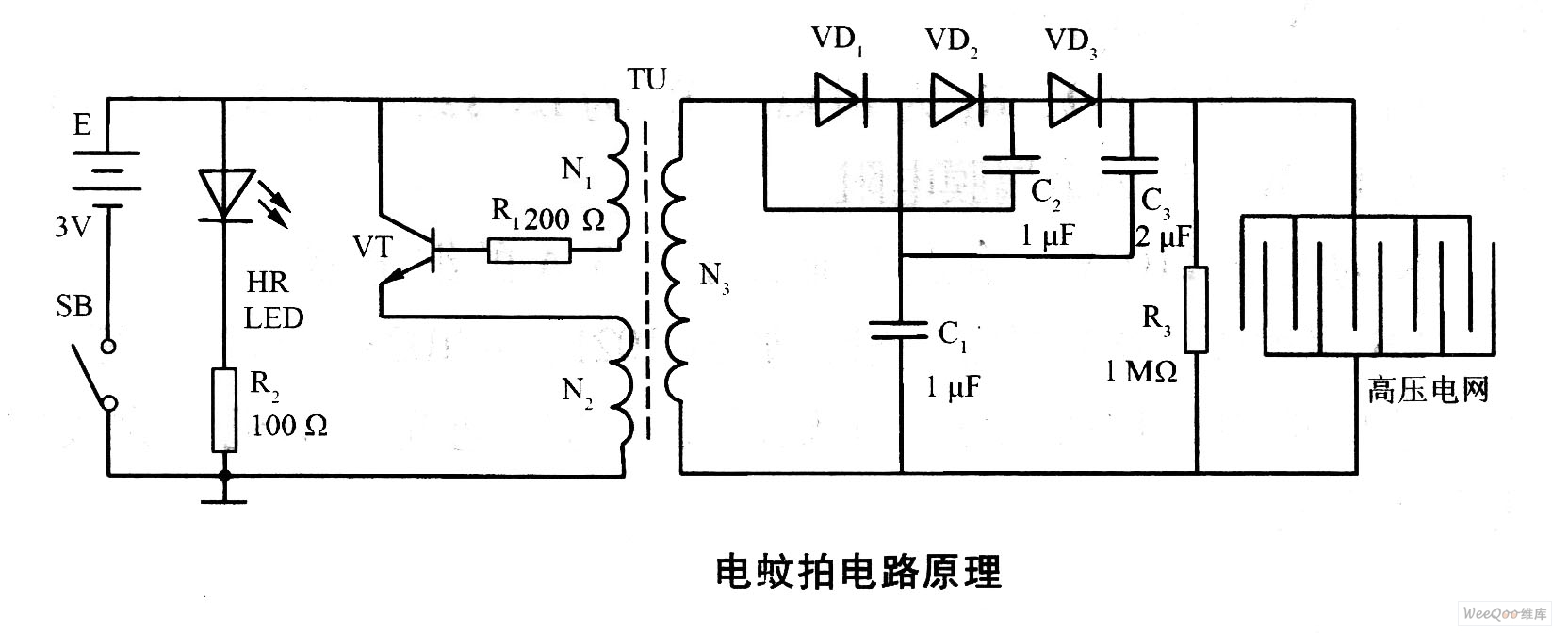
When the power switch SB is pressed, the high frequency oscillator composed of the triode VT and the high frequency transformer TU is energized, and the 3 V direct current is converted into a high frequency alternating current of about 18 kHz, boosted to about 600 V by the TU, and then The three-voltage rectification of the diodes VD2 to VD4 and the capacitors C1 to C3 is raised to about 1500 V, and is applied to the metal net of the mosquito swatter. When mosquitoes touch the metal mesh, the grid is short-circuited, and the mosquitoes are stunned and killed by powerful currents.
In the circuit, the red LED HR and the current limiting resistor R form an indicator circuit for indicating the on/off state of the circuit and displaying the loss of battery power. 
Manufactured with high quality material and built-in protection of over current, over voltage, short circuits .