Aquarium Heaters,Aquarium Glass Heater,Glass Heaters For Aquarium,Aquarium Heaters Series Sensen Group Co., Ltd.  , https://www.sunsunaquariums.com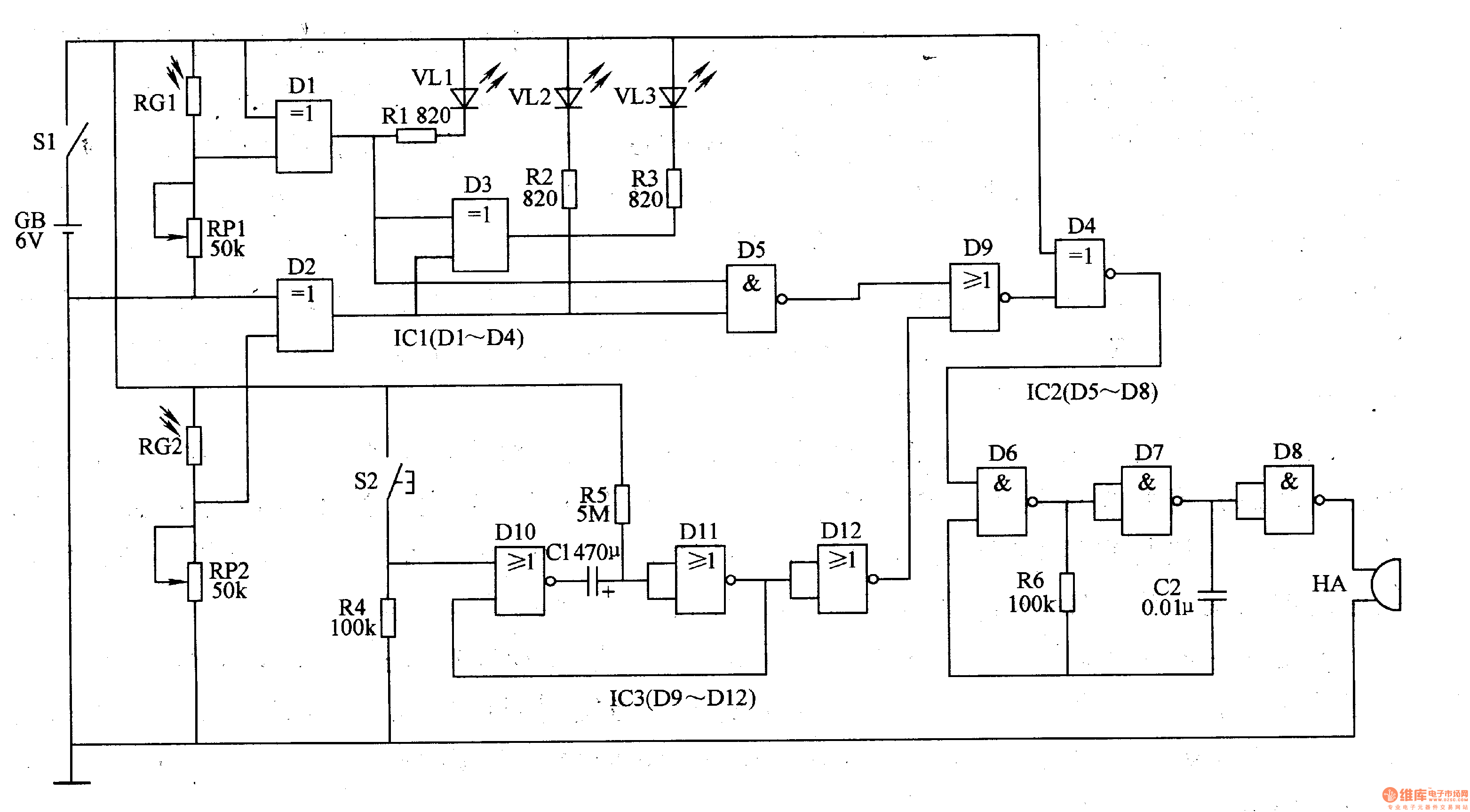
The photometric routing photo resistors RG1, RC2, potentiometers RP1, RP2 and D1, D2 inside the XOR gate integrated circuit ICl (Dl-D4) are composed.
The timing control circuit is composed of resistors R4, R5, a capacitor C1, and a NOR gate integrated circuit IC3 (Dg-Dl2).
The trigger control circuit is composed of a NAND gate D5 inside the NAND gate integrated circuit IC2 (D5-D8), a NOR gate D9 and an exclusive OR gate D4 inside the NOT gate integrated circuit IC3 (D9-Dl2).
The LED indicating circuit is composed of resistors R1-R3, LEDs VLl-VL3 and XOR gate D3.
The audible warning circuit is composed of NAND gates D6-D8, resistor R6, capacitor C2 and buzzer HA.
The photo resistors RG1 and RG2 are photodetecting elements whose resistance decreases as the illuminance becomes stronger, and increases as the illuminance becomes weaker. When the ambient light is suitable for reading and writing requirements, the XOR gates D1 and D2 both output a high level, and the XOR gate D3 outputs a low level to make VL3 light. When the ambient light is too strong, the XOR gate D1 outputs a low level to make VLl light; meanwhile, the XOR gate D4 outputs a high level, causing the audio oscillator (composed of NAND gates D6, D7 and R6, C2) to oscillate. Work, HA beeps, to remind users that the ambient light is too strong, should protect vision.
When the ambient light is too weak, the resistance of RG2 increases to make the XOR gate D2 clear, VL2A is bright; at the same time, the XOR gate D4 outputs a high level, the audio oscillator oscillates, and the HA emits a beep, reminding The user's ambient light is low and the light should be turned on.
When the timing time (3Omin) has not expired, the NOR gate Dl2 outputs a low level. At this time, if the light is suitable for reading and writing, the XOR gate D4 outputs a low level, the sound warning circuit does not work, and the HA does not sound. When the timing ends, the NOR gate Dl2 and the XOR gate D4 both output a high level, the audio oscillator oscillates, and the HA beeps to remind the user to take a break. To continue reading and writing, press button S2 to discharge C1, the timer restarts, and HA stops sounding.
Adjusting the resistance of RPl and RP2 can change the sensitivity of the metering alarm.
Component selection
Rl-R6 uses 1/4W metal film resistor or carbon film resistor.
RPl and RP2 use synthetic carbon film potentiometers or variable resistors.
Both RG1 and RG2 use a photoresistor with a light resistance less than lkΩ and a dark resistance greater than 5OkΩ.
Cl uses an aluminum electrolytic capacitor with a withstand voltage of lOV; C2 uses a monolithic capacitor.
VL1-VL3 selects φ3mm LEDs.
IC1 selects CD4070 or CC4070, MCl4070 type XOR gate integrated circuit; IC2 selects CD401l or CC4011, MCl4011 type NAND gate integrated circuit; IC3 selects CD400l or CC400l, MCl4001 type or non-gate integrated circuit.
HA uses a piezoelectric buzzer.
S1 uses a small toggle switch; S2 uses a micro-motion button.
GB uses 4 sections of the 5th battery in series.