In recent years, theft of high-end communities has been frequent. The main reasons include: First, the murder of the criminals has been refurbished, and high-tech tools have been used to open the security door locks. What is especially horrifying is that there have been news that the gangsters used tin foil to unlock more than 10 seconds. Second, most households have a weak awareness of safety and security. Nearly 10% of households have installed simple burglar alarm devices. They have lost their maintenance for a long time and are also prone to underreporting. 4.2mm Wire To Board Connectors
4.2mm Wire To Board Connectors are avialable in different terminations and sizes intended for use on a variety of applications. These connectors provide power and signal with different body styles, termination options, and centerlines. To find the wire to board set required, click on the appropriate sub section below.
4.2 mm pitch connectors wire to board connectors
Fully isolated terminals, positive locking housings, low-engagement forces and polarized housings, also offers blind mating, TPA and higher current options. Pitch 4.20mm
Circuit Board Connectors,4.2Mm Wire To Board Connectors,4.2Mm Pcb Wire To Board Connector,4.2Mm Pin Wire To Board Connector,.165" Wire To Board Connectors,4.2mm Power Connector ShenZhen Antenk Electronics Co,Ltd , https://www.pcbsocket.com
The smart home monitoring system is precisely a protective tool for criminals. It is through the voice, the Internet, mobile phone client, etc., the public can achieve efficient, convenient and diversified comprehensive communication with the government; using smart housekeeping system and remote monitoring system If the citizens are at home or on a business trip, they can use the mobile phone and computer to release the access control. In addition to going to work, they can also view the cameras in the home. This paper analyzes the circuit design of the smart home monitoring system module.
Circuit principle
1, real-time clock PCF8563 circuit
The PCF8563 is a low-power CMOS real-time clock/calendar chip that provides a programmable clock output, an interrupt output and a brownout detector, all of which are serially passed through the CI2 bus interface. The maximum bus speed is 400Kbits/s, and the embedded word address register automatically increments each time the data is read or written. The working circuit of the PCF8563 real-time clock chip is as follows: 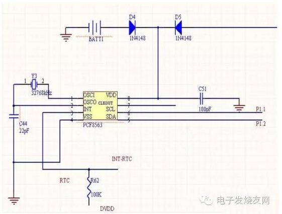
Among them, OSOI is the oscillator input, OSOC is the oscillator output, /INT is the interrupt output (open drain; active low), ssV is grounded, SDA is serial data I/O, SCL is serial clock input, CLKOUT is Clock output (open drain), DDV is positive supply.
2. Gas (smoke) detection circuit 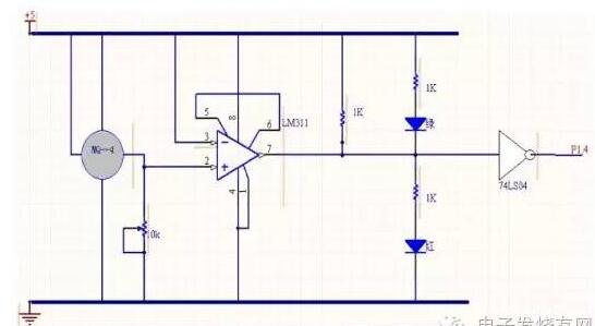
Integrated comparator LM311 constant input 5V voltage on the 3rd end, because the sensor output current is proportional to the indoor gas (smoke) concentration, ie I=kC (I is the sensor output current, C is the indoor gas concentration, k is the proportional constant) Therefore, the concentration can be converted into a voltage signal through the sensor and potentiometer 1R and input to the 2nd end of the LM311 (ie, V=kC*1R). The voltage comparator converts the analog signal into a binary signal. The LM311 is a general-purpose integrated comparator with low open-loop gain, large offset voltage, and low common-mode rejection ratio. However, its response speed is fast, the transmission delay time is short, and the high-level signal can be directly input to the microcontroller. From the above analysis, it can be known that the resistance of the potentiometer can be adjusted to adjust the upper limit of the indoor alarm concentration.
3, door magnetic detection alarm circuit 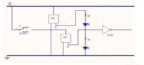
The magnetic switch 5C-31B can be set to a normally open type and a normally closed type. When it is set to start normally, the door will not be alarmed and the door will be closed. When it is set to the normally closed type, the door will open alarm and the door will not be alarmed.
4, the alarm circuit 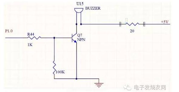
When the input terminal P1.0 has a signal input, the base of the transistor Q7 generates a current. At this time, the transistor is turned on. At the voltage of +5V, the buzzer works; when the input terminal P1.0 has no signal input, at this time, due to Q7 The base has no current, the transistor is turned off, and the buzzer stops working.
Editor's Conclusion With the rapid development of intelligent analysis technology, network technology and the improvement of people's living standards, people began to pay more attention to the safety of the home environment. With the improvement of people's needs, the intelligent real-time monitoring system should be in business. At present, the video surveillance system has experienced three stages of analog monitoring, digital monitoring and network monitoring. Although the video surveillance system was launched in the Chinese market in the late 1990s, many companies have launched their own smart home systems, but they are still popular, and the current international standards for smart homes have not yet become hot, so smart home monitoring systems There is a broad space for development.
4.2 mm pitch connectors wire to board connectors Including:
male housing
Male housing of connector, UL94V-0 and UL94V-2, hanging and panel mount, single row and dual row, 2 to 24 circuits.
Female housing
Female housing of connector, with locking latch in order to avoid loosing, and with polarity in order to avoid dis-mating. One row and dual rows, from 2 circuits to 24 circuits.
Terminal
The conductor of connector, brass or phosphor bronze, tin plated over nickel, selective gold plated as customer's requirement.
Header
Header, right angle and vertical , with peg and without peg, DIP soldering, single row and dual row, 2 to 24 circuits.
4.2 mm connectors wire to board connectors General Specification:
Current rating: 6A AC, DC.(AWG#18)
Voltage Rating: 600V AC,DC
Withstanding Voltage: 1500V AC/minute.
Insulation resistance: 1000MΩ min
Contact resistance: Initial Value/ 10mΩ max
Temperature rise: -40'C ~ 105'C.