DIP Sockets & Adapters
Precision machined Dual In-line Package (DIP) Sockets and Adapters accommodate applications from surface mount to thru-hole. Screw-machined terminals offer superior quality for long-term durability. DIP Sockets Adapters,DIP Integrated circuit Sockets,Dual In-line Package Sockets,Dual In-line Package Adapters,IC Socket, IC Sockets Adapters connector ShenZhen Antenk Electronics Co,Ltd , https://www.antenk.com
Overview of DIP Sockets & Adapters
DIP Sockets and Adapters allow for quick and easy device replacement, upgrade, or repair in test and production applications, while protecting DIP devices from exposure to heat during board processing. Screw-machined terminals with redundant, multi-finger contacts ensure reliable performance even in harsh environments.
Automated assembly compliant.
Wide range of patterns and terminal styles, from 8 to 64 pins.
Optional Tape Seal on terminals protects contacts from contaminants during board processing.
Solder Preform terminals available for mixed SMT and thru-hole process applications.
RoHS Compliant insulators and terminals are compatible with lead-free processing - select either Matte Tin/Gold (MG) or Gold/Gold (GG) plating.
Our large selection of DIP sockets ranging from 1 to 48 contacts can provide a highly reliable connection between your integrated circuit (IC) devices and PCBs. Antenk offers DIP sockets in a wide variety for high reliability. Positions range from 1 to 48, and termination options include through hole and surface mounting, solderless zero profile, four-finger inner contact and dual leaf contacts, as well as a variety of plating options.

Antenk DIP Sockets Product Features
1 to 48 positions
Precision four-finger inner contacts or dual leaf contacts are optional
Open frame and closed frame housings
Available with a variety of plating options
Four-Fingered Contacts
Precision machined or stamped four-finger inner contacts with open or closed frame housings facilitate highly reliable DIP sockets.
Dual Leaf Contacts
Dual leaf contacts provide a cost effective solution to the DIP socket design with superior handling characteristics.
**1. Introduction**
When testing microwave components, a network analyzer must be calibrated first. There are two main calibration methods: (1) Using an electronic calibration unit. This method is convenient, fast, and programmable, but it may not offer the highest accuracy, which can significantly affect the reliability of test results. (2) Manual calibration. Although this approach takes more time, it provides higher accuracy and reliability. Given that the microwave components being tested are critical parts of a key system, manual calibration is currently preferred. After calibration, the components are connected to the network analyzer via matched connectors, and an automated test program runs on the computer to record and analyze various performance parameters, automatically determining if the component meets quality standards.
**2. Hardware Components of the Microwave Component Inspection Automatic Test System**
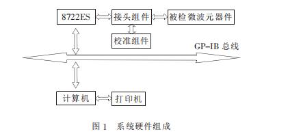
The automatic test system consists of a test instrument, a computer, a GPIB card for connecting the instrument to the host, and a printer. The main instruments include a vector network analyzer (model 8722ES), a network analyzer calibration kit, and a connector assembly. These components are interconnected via a GPIB bus, as illustrated in Figure 1.
**3. Software Design of the Microwave Component Inspection Automatic Test System**
**3.1 Selection of Programming Language for the Test Program**
There are two major categories of programming languages used in instrumentation. One is graphical programming software, such as LabVIEW by National Instruments and VEE by Agilent. These tools allow users to build programs by connecting icons, making the development process intuitive and visual. They also support data flow visualization and provide soft panels for instrument control. However, they may lack scalability and readability. Another category includes text-based languages like LabWindows and HPBasic for Windows, which are easier to integrate with other systems and offer better performance and flexibility. Considering the complexity of the test program, Microsoft Visual Basic was chosen, along with third-party controls like NI’s ComponentWorks and Agilent’s VEE.
**3.2 Requirements for the Test Procedure**
The test program should improve efficiency while ensuring accurate results. It must:
(1) Connect the test instrument to the computer;
(2) Configure the instrument settings;
(3) Read test data;
(4) Process the data;
(5) Generate a report.
**Testing Methods for Microwave Components**
For magnetron testing:
- Measure resistance between filament terminals (should be less than 1Ω).
- Check resistance between any filament terminal and the grounded magnetron (should be infinite). If low or zero, replace the magnetron.
For high-voltage transformer testing:
- Primary winding: ~1.45Ω
- Secondary winding: ~112Ω
- Filament winding: <1Ω
If readings differ, the transformer may be faulty.
The test program is written in VB, using a USB-GPIB interface and IEEE488.2 drivers. SCPI commands are used to set up the instrument, collect data, save it to a database, and generate reports after testing.
**3.3 Test Program Design**
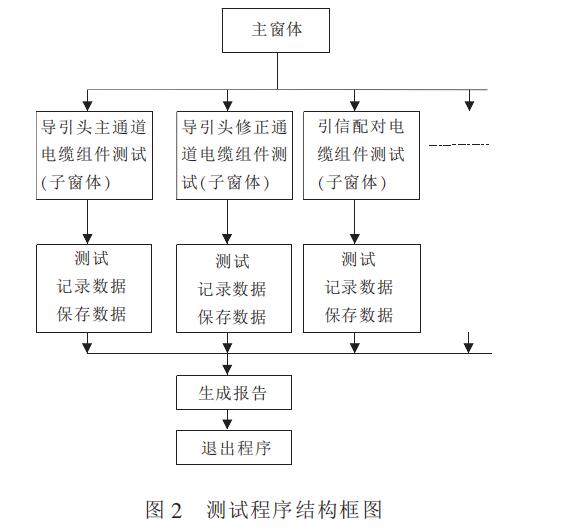
**3.3.1 Structure of the Test Program**
The program follows a top-down and modular design, ensuring each module is independent and easy to maintain. The main form contains seven buttons, each corresponding to a specific test module, including tests for seeker cable assemblies, fuse cables, waveguides, circulators, and loads.
**3.3.2 Data Processing in the Test Program**
Data collected during testing is stored in a database and compared against predefined specifications. If the component meets all criteria, it is marked as qualified. Reports are generated based on the type of component, and the number of pages is determined automatically.
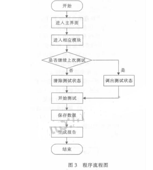
**3.3.3 How to Use the Test Program**
The program flow is shown in Figure 3. Users select a test module, run the test, and generate a report. The interface is user-friendly and efficient.
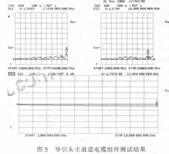
**4. Practical Application of the Test Program**
An example is the test of a seeker’s main channel cable. The test results show the VSWR and insertion loss, confirming the cable is qualified. The test interface clearly displays the results, providing reliable data for quality assurance.

**5. Features of the Test Program**
The program is highly modular, allowing reuse of common code across different modules. Each module operates independently, making the system stable and easy to expand. It also remembers the last test status, reducing setup time and improving user experience.
**6. Conclusion**
Although automation has improved efficiency and accuracy, manual installation of components still affects consistency. The variety of component interfaces (e.g., SMA, waveguide) also poses challenges. With further improvements in fixtures, the system could achieve even greater accuracy and speed.
Antenk DIP (Dual Inline Package) Sockets-Classic DIP Sockets