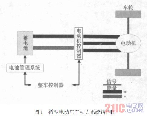
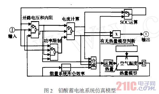
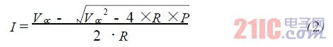
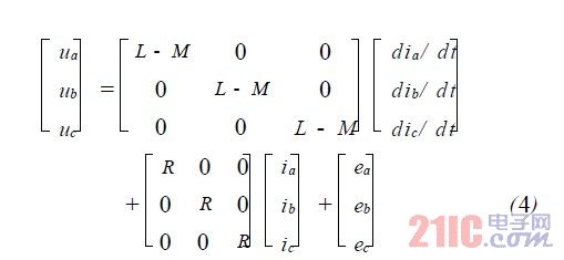
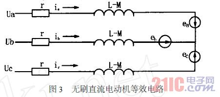
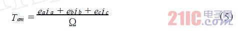
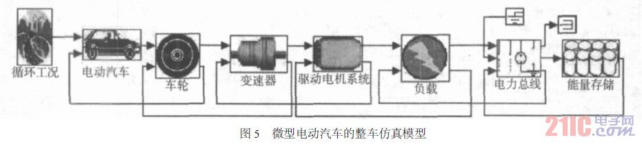
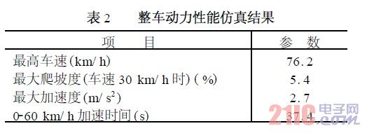
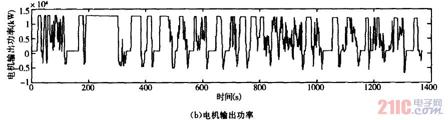
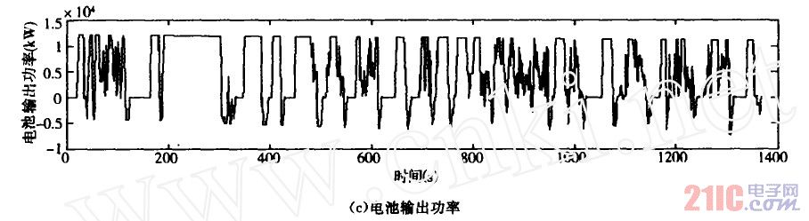
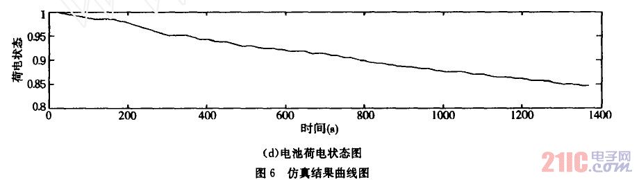
introduction This article refers to the address: http:// In order to solve the world's energy and environmental issues, the research and development of electric vehicles has received much attention. However, most of the research and development work of electric vehicles in China is based on the modification design of existing fuel vehicles. Therefore, in order to develop an economical and practical electric vehicle, it is necessary to use the advanced simulation technology to simulate and analyze its performance. Based on the modification design of a micro-fuel vehicle chassis, this paper uses ADVISOR simulation software to simulate and analyze its performance, which provides a reference for the design and industrialization of the micro-electric vehicle. 1 Power system design and main component selection The real difference between an electric car and a traditional fuel car is the power system. Electric vehicles use electric power to drive vehicles, which are powered by batteries, and convert electric energy into mechanical energy through electric motors and controllers to drive the entire vehicle. The structure of the micro electric vehicle power system modified by a micro fuel vehicle chassis is shown in Figure 1. As a power source battery for electric vehicles, it is a key component of electric vehicles, which determines the multi-faceted performance of electric vehicles. There are many types of batteries currently in use, such as lead-acid batteries, nickel-chromium batteries, and nickel-metal hydride batteries. Among them, lead-acid batteries have the advantages of versatility, mature technology, low cost, moderate specific energy, high rate discharge performance, good high and low temperature performance, etc., and thus have been widely used. The motor and drive system converts the energy of the battery into the kinetic energy of the wheel or feeds back the kinetic energy on the wheel to the battery. Electric motor motors currently being applied or developed mainly include DC motors, AC induction motors, permanent magnet brushless DC motors, and switched reluctance motors. The permanent magnet brushless DC motor not only has high weight-to-weight ratio, but also integrates electric, power generation and braking functions, high efficiency and flexible control, and has received extensive attention in the field of electric vehicles. Therefore, this paper chooses the power system composed of lead-acid battery pack and brushless DC motor to replace the internal combustion engine and fuel tank of the original fuel micro-car. 2 Establishment of simulation model 2.1 Battery System Simulation Model The simulation model of the lead-acid battery system established in this paper is shown in Figure 2. The model describes the process by which the energy stored in the battery accepts the requested power and returns the available power or actual power from the battery. It mainly includes the following modules: 1) Calculation module for open circuit voltage and internal resistance. In electric vehicle simulation, the most common battery model is the internal resistance model. The model considers the battery as an equivalent circuit with an internal resistance connected in series with an ideal voltage source. The voltage characteristics are: Where: Voc is the open circuit voltage (V); U is the battery operating voltage (V); R is the battery equivalent internal resistance (Ω). The open circuit voltage Voc and the internal resistance R in a given state of charge (SOC) and requested battery power state can be calculated from equation (1). 2) Current calculation module. The current calculation is solved by a quadratic equation, namely: Where P is power. 3) Power limit module. This module is used to limit the request power to no more than the battery power. 4) SOC calculation module. The value of the state of charge (SOC) can be calculated by: SOC=(Initial Power - Used) / Initial Power (3) Among them, the used electricity is calculated by the ampere-time integration method. 5) Thermal module. When an electric vehicle is running and charging and discharging, the thermal module is mainly used to predict the battery temperature as a function of time. 2.2 Motor and drive system simulation model The modeling basis of the motor and drive system is the balance equation of the voltage, torque and power of the motor and the equation of motion characteristics. If the winding is assumed to be completely symmetrical, the main circuit current is continuous, the magnetic resistance is constant, and the viscous friction is neglected, the voltage balance equation of the brushless DC motor can be obtained: Where: ua, ub, uc are the stator phase winding voltage (V); ia, ib, ic are the stator phase winding current (A); ea, eb, ec are the stator phase winding electromotive force (V); The resistance of each phase winding (Ω); L is the self-inductance (H) of each phase winding; M is the mutual inductance (H) between each two-phase winding. According to the voltage balance equation (4), the equivalent circuit diagram of the motor can be obtained, as shown in Fig. 3. Thus, the electromagnetic torque Tem of the motor is: Where Ω is the mechanical angular velocity of the rotor. Based on the above analysis, this paper establishes a simulation model of permanent magnet brushless DC motor and drive system, as shown in Figure 4. It consists mainly of the following four modules: 1) Speed ​​limit module. This module is mainly used to predict whether the requested speed of the motor exceeds the speed range of the motor. When vveh>vcyc, the output speed is the maximum speed of the motor; when vveh Ωa=va·ωlim/vavail Where: vcyc is the requested speed of the cycle; vveh is the vehicle speed calculated by the vehicle model; va is the actual speed; ωlim is the limited demand speed; vavail is the theoretical speed that the drive system can reach. 2) The function module of the moment of inertia. This module mainly considers the torque consumption of rotating parts such as motors. It calculates the motor inertia as a function of the vehicle's inertia based on the overall gear ratio of the drive system, and finally calculates the moment of inertia based on the input speed. 3) Torque limit module. This module mainly limits the torque requested by the motor beyond the torque range of the motor. According to the maximum torque corresponding to the maximum speed, it calculates the maximum torque when used as a motor or generator, and then obtains the maximum torque of the output according to the relationship. The modeling relationship is: when Treq>0, work In the motor state, T = min (Treq, Tmax); when Treq < 0, it operates in the generator state, T = min (Treq, Tgen · max). Where Treq is the requested motor torque; Tmax and Tgen·max are the maximum charging torque and the maximum generating torque, respectively. 4) Thermal module. This module is used to calculate the temperature of the motor and the thermal power loss of the heat sink used to maintain a certain temperature. 2.3 vehicle simulation model The simulation model of ADVISOR is directly constructed according to the layout of the actual power system. The vehicle simulation model includes sub-modules such as cycle conditions, vehicles, wheels, transmissions, drive motor systems, and energy sources. Each sub-module has a Simulink simulation module built in, and it can control the change of its parameters through the M function. The vehicle simulation model established in this paper is shown in Figure 5. 3 vehicle dynamic performance simulation 3.1 Technical parameters of the whole vehicle The main technical parameters of the modified miniature electric vehicle are shown in Table 1.     3.2 Selection of cycle conditions This paper selects the Urban Road Cycle UDDS (UrbanDynamometerDrivingSchedule) developed by the US Environmental Protection Agency as the cycle condition. The cycle time is 1367s; the driving distance is 11.99km; the maximum speed is 91.25km/h; the average speed is 31.51km/h; the maximum acceleration is 1.48m/s2; the maximum deceleration is -1.48m/s2; the dead time is 259s; the number of stops is 17. 3.3 Simulation Results According to the above technical parameters, the established vehicle simulation model is simulated by UDDS cycle conditions. The simulation results are shown in Table 2 and Figure 6, respectively. Fig. 6(a) shows the change of vehicle speed with time. The maximum speed is 76.2km/h. The simulation results show that the actual speed can track the speed of the circulating condition well. Figure 6 (b), (c) is the output power of the motor and battery energy source, the motor output power is positive and negative in the whole drive cycle, and the negative value reflects the motor operation in the state of power generation. The output power of the battery is also positive and negative, and the negative power reflects the state in which the battery is working. Fig. 6(d) shows the change of the SOC value of the battery. The tortuous curve shows that the vehicle can recover energy to charge the battery during the process of frequent acceleration and deceleration. 4 Conclusion Through the modification design of a micro-fuel vehicle chassis and the use of ADVISOR simulation software for a large number of simulation analysis, the vehicle's power system design is practical and feasible. Through simulation analysis, it can be seen that the electric vehicle can adapt to the traffic conditions of the city in terms of driving, acceleration and braking, which has important reference value for the research and development and industrialization of electric vehicles.
Wireless Ir Dimmer Sensor also can be called wireless remote controlling infrared Led Ir Sensor . The wireless smart driver connect the control box directy, then we can use Wireless Ir Dimmer to control the light. Their communication is by 2.4G.
Description of Wireless IR Dimmer
Replaceable battery operate
IR within 3years standby
PIR/Touch with 10years standby
More than 10000 times operate
Wireless switch
Easy for installation
Touch dimmer, PIR senor, IR on/off sensor, Ir Dimmer Sensor, Ir Door Sensor available.
Controlling the LED light smartly and wirelessly.
Wireless IR Dimmer Sensor Wireless Ir Dimmer Sensor,Ir Dimmer Sensor,Led Ir Sensor,Wireless Ir Dimmer Shenzhen Jedver Smart Lighting Co., Ltd. , https://www.jederwell.com