What is the minimum system of the microcontroller?
**Introduction to MCU**
A microcontroller unit (MCU) is a single integrated circuit that combines the functions of a microprocessor (CPU), memory (both program memory, ROM, and data memory, RAM), and input/output (I/O) interface circuits on one chip. This integration allows it to function as a complete, compact computer system capable of performing specific tasks efficiently and accurately under the control of a program. Therefore, an MCU contains all the essential components of a full-fledged computer.
Unlike general-purpose microprocessors, MCUs are designed for embedded applications and can perform intelligent control tasks independently. This makes them ideal for modern industrial control systems. Before the development of MCUs, similar functionality required complex electronic or digital circuits, which were less efficient and harder to manage.
An MCU differs from a single-board computer (SBC), which consists of a microprocessor, memory, and I/O chips mounted on a printed circuit board. While an MCU may appear as just a chip, when properly configured with external components, it becomes a fully functional microcomputer control system. However, it is fundamentally different from an SBC or a personal computer (PC).
The application of MCUs is at the chip level, requiring users to understand the internal structure, instruction set, and design principles of the microcontroller. This knowledge enables users to tailor the MCU for specific applications, ensuring it performs the desired functions effectively.
Each MCU has unique hardware and software characteristics. The hardware features depend on the internal architecture of the chip, while the software features include the instruction set, development tools, and support environments. These technical specifications must be studied from the manufacturer’s datasheet to ensure compatibility and proper implementation in a given system.
MCUs have replaced traditional control systems based on complex analog or digital circuits. They offer flexibility through software programming and enable intelligent control. Today, MCUs are found in various fields such as communication devices, home appliances, smart instruments, process control, and specialized control systems. Their applications continue to expand rapidly.
Beyond their practical use and economic benefits, MCUs have revolutionized traditional control methods and design approaches. They represent a major advancement in control technology and a significant milestone in the evolution of embedded systems.
**Brief Description of the Minimum System of a Microcontroller**
The minimum system of a microcontroller refers to the smallest configuration needed for the MCU to operate independently. For example, the 51 series MCU typically requires the following components: the MCU itself, a crystal oscillator circuit, and a reset circuit.
Here is a diagram of the 51 MCU minimum system:
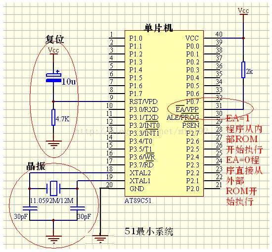
**Reset Circuit**
The reset circuit ensures that the MCU starts from the correct initial address after power-up or manual reset. It usually consists of a capacitor and resistor connected to the RST pin. When the system powers up, the capacitor charges slowly, keeping the RST pin high for a short period, which triggers the reset.
A typical value is a 10µF capacitor and an 8.2kΩ resistor. The RC time constant determines how long the RST pin remains high. For the 51 series, the reset signal needs to last for at least two machine cycles (about 2µs). If the RST pin stays high longer than this, the MCU will reset properly.
**Crystal Oscillator Circuit**
The crystal oscillator provides the timing reference for the MCU. Common frequencies include 11.0592MHz (for accurate serial communication baud rates) and 12MHz (for precise timing operations). The choice of frequency depends on the application requirements.
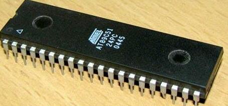
**Single-Chip Microcontroller**
The core component of the minimum system is the MCU itself, such as the AT89S51 or other compatible models from the 51 series.
**Important Note**
The EA/Vpp pin (pin 31) determines whether the MCU uses internal or external program memory. A high level enables internal ROM, while a low level selects external ROM. This detail is often overlooked by beginners.
**Working Principle of the Reset Circuit**
When the system powers on, the capacitor charges through the resistor, causing the RST pin to remain high for a short time. This initiates the reset process. When the button is pressed, the capacitor discharges quickly, causing the RST pin to go high again, resetting the system.
**Why Reset on Startup?**
During startup, the capacitor charges slowly, and the RST pin receives a high-level signal for about 0.1 seconds. This is sufficient to trigger a reset in the 51 series MCU, ensuring the program starts correctly.
**Why Reset When the Button is Pressed?**
Pressing the reset button creates a short circuit across the capacitor, discharging it and causing the RST pin to go high again. This triggers another reset, allowing the system to restart.
**Summary**
1. The reset circuit works by maintaining a high-level signal on the RST pin for more than 2µs.
2. Pressing the reset button discharges the capacitor, creating a high-level signal on the RST pin, thus resetting the system.
**Introduction to the 51 MCU Minimum System Circuit**
1. The reset circuit's capacitor polarity affects the reset time. A typical range is 10~30µF. Smaller capacitors result in shorter reset times.
2. The crystal oscillator can use frequencies like 6MHz or 11.0592MHz. Higher frequencies improve processing speed.
3. Capacitors C2 and C3 (usually 15~33pF) should be placed close to the crystal oscillator for better stability.
4. The P0 port requires pull-up resistors (typically 10kΩ) due to its open-drain output.
When operating in timer mode, the counter counts the internal machine cycle (1 machine cycle = 12 oscillator cycles). The timing duration is calculated as N × Tcy, where N is the count value and Tcy is the machine cycle time.
In counter mode, external pulses are counted through the T0 or T1 pins. The counter increments only when a falling edge is detected. The maximum counting frequency is limited to 1/2MHz at 12MHz crystal frequency.
110KV-220kv Oil Immersed Transformer
110Kv-220Kv Oil Immersed Transformer,Anti - Interference 110Kv Transformer,Low Loss 110Kv Oil-Immersed Transformer,High Load Capacity 110Kv Oil-Immersed Transformer
Tianhong Electric Power Technology Co., Ltd , https://www.tianhongtransformer.com