1 Introduction
Compared with mechanical buttons and resistive touch buttons, capacitive touch buttons are not only durable, low cost, simple and easy to install, waterproof and stain resistant, but also provide functions such as rollers and sliders. However, capacitive touch buttons also have many problems. Because there is no mechanical structure, all the detections are small changes in the amount of electricity, so they are much more sensitive to various disturbances. ST has introduced a capacitive touch sensing solution based on the STM8 series of 8-bit general-purpose microcontroller platforms for home appliance applications, especially for induction cooker applications. The capacitive touch sensing function can be realized with a simple peripheral circuit without adding a dedicated touch chip. Convenient for secondary development.
2 Program introduction
ST's capacitive touch button solution detects the change in capacitance caused by human touch through the charging/discharging time of the RC network formed by a resistor and a capacitor CX of the sensing electrode. As shown in FIG. 1, when a human hand is pressed, a capacitance CT is connected in parallel to the sensing electrode, which increases the capacitance on the sensing electrode, and the time during which the sensing electrode performs charging and discharging increases, thereby detecting the state of the button. The sensing electrode can be directly drawn on the PCB as a button, roller or slider. It can also be inserted into the PCB, even if it is insulated (glass, resin). Has an impact.
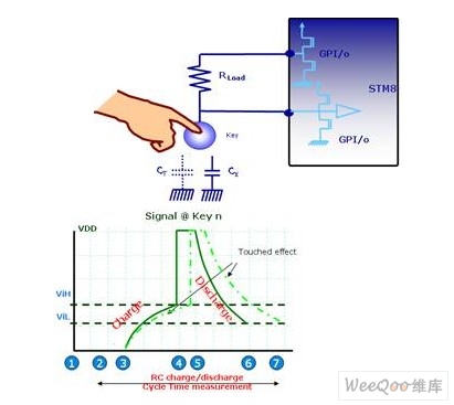
Figure 1 STM8S capacitive touch button works
The induction cooker heats the food by the heating principle of the magnetic field induced current. When heating, a strong magnetic field is generated through the coil below the panel. When the magnetic flux passes through the bottom of the pot made of the magnetic guide, the pot cuts the alternating magnetic field lines and generates eddy current at the bottom of the pot to rapidly heat the bottom of the pot to achieve the purpose of heating the food. In this solution, the 44pin STM8S105S4 is used as the main control chip of the button display panel, which controls the scanning of 13 buttons, the display of 24 LEDs and a 4-digit digital tube, the communication between I2C and the motherboard, and has a convenient SWIM interface. Engineer debugging (Figure 2).
STM8S105S4 adopts ST advanced STM8 core, with 3-stage pipelined Harvard architecture, 3.0~5.5V working voltage, internal 16MHz RC can provide MCU 16MHz operating frequency, provide low power mode and peripheral clock off function, there are 34 I /O is available. The STM8S105S4 has 2KB of RAM and 16KB of FLASH, as well as 1KB of EEPROM data memory up to 300,000 erases.
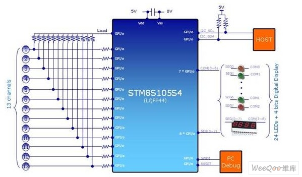
Figure 2 Principle of the induction cooker keypad
3 Interference in the working environment of the induction cooker
Electromagnetic interference
While the induction cooker is heating the pot, it also senses the current in the forward or reverse direction of the induction electrode on the circuit board, which will shorten or increase the charge and discharge time of the button, which will greatly affect the detection of the button and even cause malfunction. Common methods Hardware shielding and zero-crossing detection are used to eliminate the effects of electromagnetic radiation on the buttons.
Hardware shielding
In the STM8S solution, the ST provides the design specifications for the sensing electrodes and traces and the Driven Shield function shown in Figure 3. (Provides the same drive signal on the Shield line as the button pins, parasitic between the electrodes and the Shield The capacitor will not be charged and discharged), which can effectively reduce the influence of the parasitic capacitance of the sensing electrode trace on the sensitivity of the button.
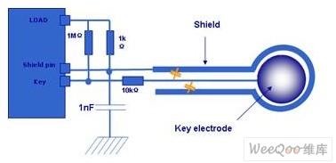
Figure 3 Driven Shield
Zero crossing detection
1) Hardware zero crossing detection
The zero-crossing detection can be implemented by hardware. In the hardware design, the hardware detection circuit of the zero-crossing point of Figure 4 or Figure 5 can be added. When the output of the B terminal is high, the state of the button is judged, so that the electromagnetic radiation is minimized. The touch button is detected.
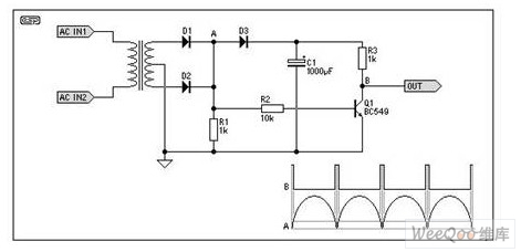
Figure 4 hardware zero-crossing detection circuit 1
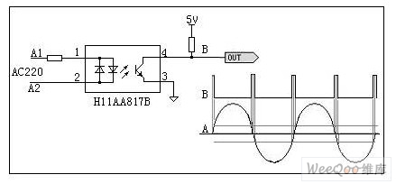
Figure 5 hardware zero-crossing detection circuit 2
2) Software zero crossing detection
Hardware zero-crossing detection increases the complexity of hardware circuit design and increases the cost of the solution. In our solution, for the working environment of the induction cooker, we use software to perform zero-crossing detection, thereby reducing the cost and effectively solving the touch key of the main power circuit of the induction cooker. Interference
2. Grid interference
Because the quality of the domestic power grid is different, in some areas with poor quality, it is easy to affect the normal operation of the touch button of the induction cooker. If you can't do power isolation, you will see the difference in Figure 6 (blue means no button, red means button is pressed), and these figures are only when the induction cooker has no power, when the induction cooker works The electromagnetic radiation will make the signal seen more chaotic. In the experiment, it was found that by using the isolation from the external power grid or using software filtering, the button effect can be significantly improved.
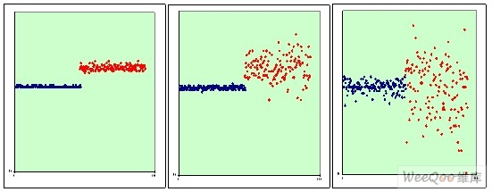
Figure 6 Good quality grid Poor quality grid 1 Poor quality grid 2
3. Splashing water, the effect of splashing oil
In the use of induction cooker, water or oil splashes on the touch panel, which may cause the button to be triggered by mistake. This solution uses a special software algorithm to reliably separate the water splashing from the finger press.
4. Environmental adaptive ability
When the induction cooker is working, it will generate a lot of heat and moisture. The panel temperature/humidity, board temperature/humidity will float in a wide range, and with the passage of time, including glass panels and PCB boards. The aging of different programs will occur, which will affect the accuracy of button detection. In the ST solution, an automatic calibration function is implemented to provide environmental detection in real time and to implement an environment adaptive mechanism.
4 summary
The solutions provided by ST include touch panel self-calibration, software filtering, software zero-crossing detection and environmental self-adaptation. The software algorithm is used to shield the interference of various complex environments as much as possible, with low cost and reliable operation. Of course, in other applications, there are some different requirements from the induction cooker environment. Here are just some of the representative interferences, but as long as you master the working principle of capacitive touch, there are still many ways to deal with each. Application situation.
:
6 times
Window._bd_share_config = { "common": { "bdSnsKey": {}, "bdText": "", "bdMini": "2", "bdMiniList": false, "bdPic": "", "bdStyle": " 0", "bdSize": "24" }, "share": {}, "image": { "viewList": ["qzone", "tsina", "tqq", "renren", "weixin"], "viewText": "Share to:", "viewSize": "16" }, "selectShare": { "bdContainerClass": null, "bdSelectMiniList": ["qzone", "tsina", "tqq", "renren" , "weixin"] } }; with (document) 0[(getElementsByTagName('head')[0] || body).appendChild(createElement('script')).src = 'http://bdimg.share. Baidu.com/static/api/js/share.js?v=89860593.js?cdnversion=' + ~(-new Date() / 36e5)];
The Taihang Jiaxin charger is controlled by a solid-state thyristor with electronic sensing and monitoring functions. The main function of the charging system is to charge the battery without supervision while providing a continuous load. The charging characteristic is a constant potential with a current limit. The charger rectifier circuit provides 100% of the rated current, while the float/boost charges a group of lead-acid batteries. The system is also suitable for maintenance and non-maintenance operations.


Battery Charger
Battery Charger,Lipo Battery Charger,Hf Battery Charger,Three Stage Battery Charger
Xinxiang Taihang Jiaxin Electric Tech Co., Ltd , http://www.agvchargers.com