The proliferation of portable products such as mobile phones, portable media players, handheld game consoles and digital cameras has put system designers under increasing pressure. They must constantly develop products that offer new features and functionality, and minimize time-to-market. So, what benefits does CPLD offer for portable design? What are the main design factors to consider when choosing a logical solution for a portable application? This article refers to the address: http:// Board Size As portable products shrink in size, designers must integrate more logic on very small boards. Today's CPLDs are available in ultra-small packages, including chip-scale BGAs (csBGA, 0.5 mm pitch), which require only 25 square millimeters or 49 square millimeters of board space. A conventional thin quad flat package (TQFP package, 0.8 mm pitch) package requires a board area of ​​100 square millimeters or 196 square millimeters.
Led Ufo High Bay light using Samsung led light source, providing excellent lumen output, long-lasting stability and splendid sight. Fins convection heat radiating design, enlarge heat radiating area, improve heat radiating efficiency and ensure safety. Thickening aluminum cover with high quality surface painting treatment and strong corrosion resistance. PMMA integrated lens enable a wide lighting area and excellent dustproof performance. Intelligent waterproof driver, rated IP65, CE qualified, with overload, undervoltage and convection protection. Led UFO High Bay light are an ideal lighting solutions for outdoor like street, dock, station, construction site etc.
Led UFO High Bay Led Ufo High Bay,Led High Bay,Ufo Led High Bay,Industrial Led High Bay Light Guangdong guangzhidian lighting Co., Ltd. , http://www.gzdlighting.com
Handheld products are widely used, such as the proliferation of portable products such as mobile phones, portable media players, handheld game consoles and digital cameras, which are putting more and more pressure on system designers. They must constantly develop products that offer new features and functionality, and minimize time-to-market. According to market intelligence firm iSuppli, revenue from core semiconductor products in these areas is expected to grow from $26 billion in 2008 to $30 billion in 2012, equivalent to a compound annual growth rate of 4% (core device is from iSuppli) Defined, such as ASSP, ASIC and programmable logic devices).
Because of the low standby power requirements, small board size, and low cost, the logic functions of portable products used to be provided by application-specific integrated circuits (ASICs) and application-specific standard products (ASSPs). The application of programmable logic devices (PLDs) is equivalent. limited. However, as programmable device architectures improve, power consumption decreases, and new packages reduce size and cost, designers are increasingly using PLDs because PLDs are compared to ASICs and ASSPs. It has an inherent advantage in reducing time to market and design flexibility.
CPLD Applications In portable products, Complex Programmable Logic Devices (CPLDs) are typically used for power-up sequencing, level shifting, timing control, interface conversion, I/O expansion, and discrete logic functions. The CPLD can be powered up in just a few microseconds, which allows it to control the power-up sequence of other devices in the system.
In portable systems, CPLDs are also used to connect multiple devices with different operating voltages. For example, in a mobile phone, the microcontroller needs to be connected to peripheral devices, timers, and memories that operate at different voltages. The latest generation of CPLDs can be connected to different voltages between 3.3V and 1.5V because they have a core supply voltage (Vccint) that is independent of the output voltage (Vccio). Each I/O bank of the CPLD can be configured to operate independently of the logic device interface. Figure 1 shows the function of a CPLD in a typical portable system. 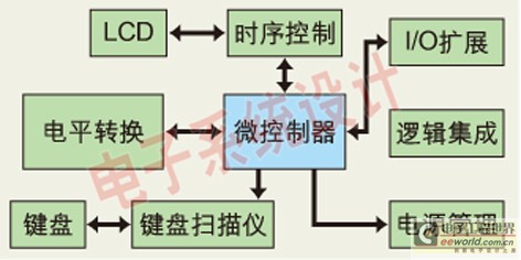
Figure 1: The function of a CPLD in a typical portable system.
Generic I/O extensions are another area where CPLDs can work in conjunction with microcontrollers, ASICs, or ASSPs, increasing the total number of available I/Os. An additional advantage of CPLD is its ability to interface with peripherals and repeat programming. CPLDs can also be used for interface conversion, connecting different interfaces such as I2C, SPI, and memory, as well as timing control of liquid crystal panels in portable systems.
When choosing a logic solution for a portable application, the key factors designers should consider include time to market, design flexibility, standby power consumption, board size, and system integration options.
Product lifecycles with shorter time-to-market and design flexibility present new challenges for handset designers who must deliver new products and features that consumers expect. For high-volume products, ASICs may offer lower unit prices, but ASIC's one-time engineering cost (NRE) is high and development time is long. If the ASIC fails to function, or if the design needs to be redeveloped due to changes in industry standards or market requirements, it will again incur very high costs, including engineering resources, new masks, and software design tools. In addition, from the beginning of the implementation of the new modification to the flow of film, to mass production, this process takes a long time, usually months to a year.
Compared to ASICs, ASSPs have lower NREs because many customers are using them. However, they limit the ability of designers to provide product differentiation.
CPLDs enable designers to develop, test, and modify designs as they wish, without incurring any masking or design costs. Thanks to the reprogrammable nature of the CPLD, designers can use software design tools to correct errors and upgrade products at the last minute, even if the device is already installed on site. As a result, designers can respond to changing requirements and standards and quickly deliver new differentiated products to the market without any design or redesign of the board.
The power consumption of a power CPLD is usually divided into two parts: static power and dynamic power. Static power is the power consumed in the absence of a signal transition in the device. Dynamic power is the power consumed in a device with a signal transition and is proportional to the internal capacitance, the jump frequency, and the jump voltage. Standby time is a key design factor for portable systems because designers minimize the static power consumption of the logic to maximize the time between battery charging or replacement. Today's low-power CPLDs have a maximum static power consumption of 10 to 150uA, depending on the logic density of the device.
To further reduce overall system power consumption, some CPLDs allow the user to selectively turn off unused input pins (called "input strobes"), including enabling complex I/O pins and input buffers. The device, and its associated circuit within the CPLD (as shown in Figure 2). When the enable signal is activated, all inputs are isolated or turned off so that any input changes do not cause internal pin changes. Therefore, even if the input of the I/O pin is changing, it does not affect the internal dynamic power consumption of the device. 
For example, in Lattice's ispMACH 4000ZE CPLD, all I/O pins in a block share a PowerGuard (for input strobes, Lattice gives the name of this feature) enable signal, called block input. Enable (BIE) signal. The BIE can be generated internally by macrocell logic or by user I/O from an external source or input pin. To increase the flexibility of the design, how many blocks of input enable signals are available in the device, ranging from 2 to 16. Two or more enable signals can be combined to form a user enable signal.
Taking the 6 macrocell ispMACH406?ZE device as an example, except for the two active inputs, the rest use PowerGuard, which reduces the dynamic current by 99%. As shown in Figure 3, the dynamic ICC is reduced from 2.9 mA to 26 micro amps. 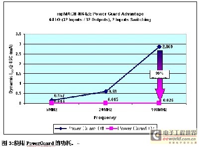
Some CPLDs can individually control each pin to "high" or "low" by software, further reducing I/O current and total system power. Input hysteresis circuits with typical voltages from 250mV to 500mV are typically used to achieve noise reduction and slower input signal changes to improve signal integrity.
Since the main system power supply is typically 1.8V, most portable systems require an LVCMOS interface. These systems are required to interface with other devices operating in the TTL or LVCMOS standard. All CPLDs currently have separate core voltages and I/O voltages, with I/O voltages supporting 1.5, 1.8, 2.5, and 3.3V LVCMOS levels. CPLDs such as the ispMACH 4000ZE can also interface with traditional 5V voltage LVCMOS devices.
These packages are ideal when board space is limited. These packages reduce board space by more than 75% compared to traditional TQFP packages, simplifying board layout and reducing overall system cost. Figure 4 is a schematic diagram of the ispMACH 4000ZE csBGA package. BGA package thermal resistance values ​​(typically 10 degrees / watt) are lower than TQFP or PQFP packages (typically 20 degrees / watt to 40 degrees / watt) for better power consumption and improved device reliability, they are better s Choice. 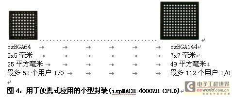
System integration reduces overall system cost by reducing components on the board. When multiple board components are used, manufacturing costs, including assembly, packaging, and shipping, add to the overall board cost. In addition, the more components on the board, the higher the failure rate due to residue and other random faults between the solder balls.
Reducing components can also reduce power consumption. Today, low-power CPLDs are used to integrate external clock sources with standard discrete logic devices such as the 7400 Series logic devices. A single programmable logic device can be used to integrate multiple discrete 74xxx devices and perform other functions such as I/O expansion, level shifting, and timing control.
For system integration, the ispMACH 4000ZE CPLD features an on-chip user oscillator and timer, keyboard scan and display controller functions for power-up sequencing, in addition to macro cells with 32 to 256 logic densities on the device. The oscillator output typically has a frequency of 5MHz and can be further divided into 128 (7-bit), 1024 (10-bit) or 1048576 (20-bit) to operate at lower frequencies. The benefits of using an integrated oscillator within the CPLD are the ability to reduce board cost, simplify inventory management, and minimize the risk of product expiration, often associated with the use of discrete components. The table below compares the latest generation of CPLD series available for portable systems. 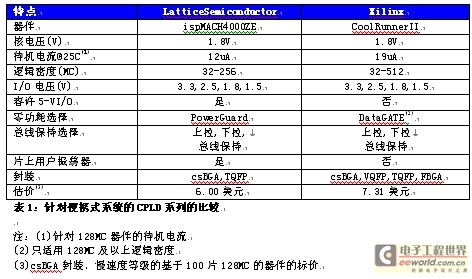
Comparison of CPLD series for portable systems.
Summary CPLDs are increasingly being used in portable products with zero standby power options, space-saving ultra-small packages, and enhanced system integration. Compared to ASICs and ASSPs used in the past, CPLDs offer designers a low-cost system solution with significant advantages. In addition, CPLD enables designers to add new features and functionality to consumers' needs in less time, making them faster to market and less risky.