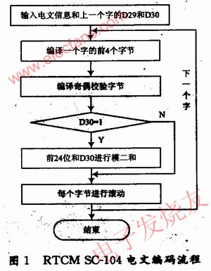
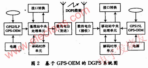
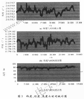
O Introduction The precision positioning service (PPS) of the GPS system is not open to the public, and ordinary users can only use the standard positioning service (SPS) of the C / A code, although the US government has canceled the implementation of the optional availability (SA) policy and the GPS using the C / A code The receiver positioning accuracy can reach 25 m (95% confidence level, two-dimensional horizontal plane error), but it still cannot meet the needs of some systems. Differential GPS technology can improve the real-time positioning accuracy and obtain meter-level or even sub-meter-level positioning accuracy. The International Maritime Radio Technical Committee (RTCM) established the SC-104 special committee for differential GPS services in 1983 to discuss various methods for providing differential GPS services and formulate data format standards. At present, GPS receivers produced by various GPS manufacturers, except for preparing their own special formats, basically have a differential data interface that conforms to the RTCM SC-104 standard format, and the price of the receiver is becoming more and more reasonable today in the fierce GPS competition. And because the current differential GPS reference stations that can send RTCM SC-104 messages are produced by foreign manufacturers, the price is expensive, up to tens of thousands to hundreds of thousands of yuan, and the price of GPS-OEM (original equipment manufacturer) board is cheap, insufficient It can be bought in thousands of yuan, and it is more flexible to use. The DGPS reference station designed by GPS-OEM board can also achieve higher positioning accuracy, so it has great practical value. 1 Principle of pseudorange differential GPS Pseudo-range differential GPS has many advantages, such as high accuracy, and is the most widely used differential GPS technology. RTCM SC-104 standard and differential positioning of almost all GPS receivers use this technology. In the pseudorange differential GPS system, the reference GPS receiver can accurately find the geocentric coordinates of the reference station, and collect the ephemeris files of all satellites, calculate the geocentric coordinates of all visible and stars at each moment, so as to obtain each The real distance Rj from the satellite to the reference station, and the reference GPS receiver measures the pseudorange of all visible satellites Where: △ tb is the clock difference of the base station receiver; It can be seen from equation (6) that the corrected pseudorange basically eliminates satellite ephemeris error, satellite clock error, ionospheric delay and tropospheric delay, and the mobile station receiver uses the corrected pseudorange for positioning and calculation. Get more accurate positioning results. The differential GPS reference station is to complete the calculation of the differential correction number and the change rate of the correction number of all visible satellites, and broadcast to users within a certain range according to the RTCM SC-104 standard format, so that it can obtain higher positioning accuracy. 2 RTCM SC-104 message and its compilation The RTCM message is composed of several binary words, each 30 b word is divided into 5 6 b bytes, of which the first 4 bytes are used to transmit differential data information, and the fifth byte is used for parity check, so that The user verifies that the received data is correct. RTCM message adopts 6/8 (1 ~ 6, 1 is the least significant bit) for data transmission, the 7th bit is the flag bit, set to 1, and the 8th bit is set to space. This encoding rule is valid for RTCM bytes between 64 and 127, because 1000000 in binary is equivalent to 64 in decimal, and 1111111 in binary is equivalent to 127 in decimal. Any bytes greater than 127 and less than 64 are invalid for RTCM. . RTCM messages can be serially transmitted between the standard computer universal asynchronous transceiver UART. Since UlART is an agreed asynchronous communication, the least significant bit is sent and received first, and each byte must be "rolled" before being sent. This has an effect. The logical sequence of RTCM messages is maintained so that the most significant bit takes precedence in the transmission medium. Assuming that a byte is represented by d1, d2, d3, d4, d5, and d6, the meaning of rolling is d1 and d6, d2 and d5, and d3 and d4 are interchanged. According to the foregoing, the entire encoding process can be roughly summarized as: (1) Acquire the content of message information. Including the type of message and the information content that the message must contain, because the format of each message will be different due to the different content transmitted. (2) Compile the first 4 bytes of each word. When compiling the first 4 bytes of each word, you must first understand the content of the message information contained in these 4 bytes. At the same time, you must know the number of bits and the location of each type of information, and compile in the order of the location. (3) Compile the 5th byte of each word, namely the parity check code. After the content of the first 4 bytes is compiled, the content of the 5th byte is compiled according to the parity check algorithm. At the same time, the last two values ​​of this byte must be reserved for the encoding of the next word. This is a very important part of the RTCM message encoding, which enables the user to verify the received information. (4) Perform a modulo-two sum of each bit of the first 4 bytes and the last bit of the previous word. The modulo two sum is an addition in binary, but does not take a carry. (5) Complete the scrolling of each byte. After the rolling of each byte is completed, the message can be sent to the mobile user through the radio station. The above mentioned is a one-step encoding procedure for RTCM messages. For a certain message of RTCM, the header of the message is compiled first, and then the main part of the message is compiled. Figure 1 is a flowchart of the entire coding program. 3 Design of DGPS system based on Garmin GPS-OEM template The GPS receiver OEM boards of the models GPS25LP and GPSl5L produced by the Garmin company in the United States are 12-channel C / A code single frequency receivers. GPS25LP has two RS 232 serial data communication interfaces, which provide ASCII code navigation message output and binary raw measurement data output. GPS25LP receiver can be used as a base station GPS receiver after correct setting. The GPS15L receiver can input real-time differential correction data (RTCM SC-104 information type 1, 2, 3, 7, 9) through the serial port 2 interface and can be used as a mobile station. Using two GPS-OEM templates and other related equipment, a simple differential GPS positioning system can be established. Its system structure is shown in Figure 2. When GPS25LP-OEM is used as a reference station, it mainly completes the reception of ephemeris data and GPS measurement data of the reference station; the central processing unit of the reference station performs the calculation of the differential correction number and encodes the RTCM SC-104 message format; The transmission and reception of the mobile station; the mobile station GPSl5L-OEM completes the decoding of the message format, combined with the GPS measurement data received in real time to generate high-precision GPS positioning information. 4 Test results At a static fixed position of the antenna (longitude 1: 28.232 068 °; latitude 1: 112.991 309 °, height 1: 78.460 089 m; longitude 2: 28.232 075 °, latitude 2: 112.991 282 °, height 2: 84.728 061 m) The differential system established by GPS25LP and GPSl5L and the HemisphereHCl2-A differential system simultaneously observe GGA data for nearly 10 hours. The statistical diagrams of the longitude, latitude, height and time of the self-built simple differential system are shown in Figure 3. Using the GGA Parse 5.5 solution software of Beijing Hezhong Sizhuang Company, the following test data comparison is obtained, as shown in Figure 4 and Figure 5. As can be seen from the statistical data and software calculation of the coordinate data, the positioning accuracy of the self-built simple differential GPS system can be maintained within 4 m. 5 Conclusion According to relevant theoretical analysis, the use of pseudorange differential positioning can eliminate common errors such as satellite clock errors, orbital parameter errors, ionospheric effect errors, and tropospheric effect errors. The remaining target carrier distance measurement errors mainly come from the channel and noise of the receiver Part of the propagation environment error that is different from the ground multi-effect and the satellite signal propagation path is different. The experimental results verify that the differential measurement system using GPS25LP and GPS15L as differential reference stations and mobile stations, respectively, has high positioning accuracy and can provide meter-level accuracy of positioning information for many precise measurements; Very high, with high use value.
1.2L Food Choppers since they are moderate in size, many people will choose them. They not only can chop vegetables, but also can chop a lot of meat. And 1.2L food choppers have glass bowl and stainless steel bowl optional.
Description for 1.2L Food Choppers
300W/350W
with dobule blades
1 speed easy to control
Carton box: 60.5*41*26.5cm 6pcs/ctn
20'GP: 2646pcs 40'HQ: 6294pcs
1.2L Food Choppers 1.2L Food Choppers,1.2L Choppers,Best Food Chopper,Glass Food Chopper Machine Flying Electronic Co., Ltd , https://www.flyingelectronic.com![]() for:
for: 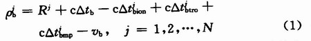
![]() It is the satellite ephemeris error and satellite clock difference;
It is the satellite ephemeris error and satellite clock difference; ![]() Is the ionospheric delay;
Is the ionospheric delay; ![]() Tropospheric delay;
Tropospheric delay; ![]() For multipath effect delay; vb is the receiver measurement error. The measured pseudorange contains various errors, which are different from the true range. This error is the pseudorange correction number:
For multipath effect delay; vb is the receiver measurement error. The measured pseudorange contains various errors, which are different from the true range. This error is the pseudorange correction number: