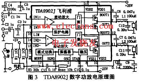
TDA8902J digital power discharge schematic diagram: Figure 3 is the TDA8902J digital power discharge schematic diagram. In the figure, Rosc is a timing element that determines the oscillation frequency. Rosc can be obtained as 3 × 10 / fs. The value range in the parameter table is 100kHz and 500kHz, and the recommended value is 300kHz. From this, Rosc can be calculated as 10kO. TDA8902J digital power discharge principle diagram
Porcelain insulation
Porcelain Insulator is made of ceramic materials. The surface of porcelain is usually covered with enamel to improve its mechanical strength, waterproof and wet, and increase the surface smoothness. The combination of porcelain and other minerals allows current to pass without reacting with nearby electrical conductors. Ensuring greater safety, High Voltage Porcelain Insulators also allows current to pass without losing any power. There are several types ofHigh Voltage Porcelain Insulators and low volatage porcelain insulators : Switch Post Insulators, Din Insulators , Line Post Insulator , Station Post Insulator, Disc Insulator , Pin Insulator , Long Rod Insulator , Porcelain Bushing , Strain Insulator , spool insulator, Shackle Insulator and Telephone Line Insulator.
We warmly welcome friends both domestic and abroad to visit our company, if you have any questions, please contact with us directly.
Porcelain Insulator Porcelain Insulator ,High Voltage Porcelain Insulators,Switch Post Insulators,Din Insulators FUZHOU SINGREE IMP.& EXP.CO.,LTD. , https://www.cninsulators.com
C3 is the grounding capacitance of the feedback circuit, the feedback resistance gown has been made in the IC
Inside the chip. The two together form a first-order low-pass feedback circuit, which has a negative feedback effect on signals below the switching frequency. The shown capacitance is the relative value when fS = 300kHz. Due to the external use of C6 and C7 as bootstrap capacitors, the switching frequency MOSFET in the PWM function block is connected in a half-bridge form. The protection circuit has overvoltage protection, output overcurrent protection, and thermal shutdown functions. It is safe to use.
This circuit also has auxiliary functions such as mute / standby. The standby function uses an external control signal to turn off the internal oscillator, cut off the power supply current when there is no signal, and reduce the standby current to 3mA. The function control of the three states of the standby sound pressure is achieved by inputting three different voltages to the (17) th pin.
Another key component in the circuit is passive low-pass filtering Ll, Cl2 and L2,
Cll. Their value is based on the impedance of the speaker and the frequency required to pass
fc and the Q value of the circuit are required to be determined. Here L1 = 100 UH, C10 =
0, 39 UF, RL: 8R, can be calculated fc = l / 27c (LC) / 2 = 24khz, Q =
RLC / L = 0,03. If RL-5fl and fc remain unchanged, the Q value will become 0.02. general
The Q value is small, the circuit is relatively stable; the Q value is equal to 0, 04 is the most flat response, cut off