Small robot soccer fusion mechanical design, automatic control, wireless communication, image recognition, intelligent body design and many other technologies have become a very attractive hot spot in the field of robot research. The robot soccer game system is a closed-loop control system, which is generally composed of four subsystems: decision making, robotic car, visual and wireless communication. Among them, the wireless communication system is an indispensable link between the connection between the host and the underlying robot. Its main task is to transmit the control commands of the decision system to each robot in real time. The robot makes corresponding commands according to the instructions of the decision system. Actions, whose communication performance is good or bad, will seriously affect the robot's movement and the smooth progress of the game. Since the robot soccer game is a dynamic and fast real-time system, the wireless communication system is required to have high communication speed, stability and anti-interference. In addition, the size of the communication module should also be adapted to the requirements of miniaturization of soccer robot cars. Therefore, the development of a wireless communication system with high communication rate, good integration, high reliability and strong anti-interference ability is of great significance for winning the game. In order to improve the performance of communication system, this paper designs and develops a high-speed wireless communication system based on PTR6000.
1 Soccer robot wireless communication mechanism and selection of communication hardware
According to the rules of the game, the communication between the host and the robot car is wireless, and the wireless channels of the two teams are different. The wireless communication system is responsible for outputting the control command formed by the host decision-making mechanism to the wireless transmitter through the computer-controlled serial data, and transmitting it after modulation, and the receiving module on the robot car demodulates the command information contained on the wireless signal, and then transmits For the on-board microprocessor to further process, each robot must filter its own command information according to its own program.
As the air interface of wireless communication, the selection of communication chips directly affects the efficiency and reliability of system communication. According to the requirements of the system for the wireless communication device, such as frequency selection, high communication rate, reliable performance, small size, etc., the system selects the PTR6000 module of Norwegian Nordic company nRF2401 chip as the wireless data transceiver module. It works in the 2.4 GHz ISM band developed globally, with a communication rate of up to 2 Mb/s, with 125 channels to meet the needs of multi-frequency and frequency hopping. The other half-duplex wireless transceiver is integrated, so the communication method is flexible; It requires less external components and simple interface circuit, so it is especially suitable for the miniaturization of soccer robots; it can be directly connected to the serial port of single-chip microcomputer, and can also be connected to the RS 232 serial port of PC. The software programming is very convenient; the anti-interference ability is strong; the power consumption is small.
2 Design of hardware circuit of wireless communication system
2.1 Transmitter design
In the wireless transmitter, the core components adopt AT89LS52 single-chip microcomputer and PTR6000 ultra-high frequency wireless transceiver module, which is matched with level conversion circuit and logic circuit. The circuit diagram is shown in Figure 1. As can be seen from the figure, the RXD port of the AT89LS52 receives the data signal from the PC. By initializing the PTR6000, it operates in the transmitting state. The ShockBurst mode defines the packet format and simultaneously passes the data through the CE, CLK and DATA three-wire interfaces. Launched to achieve data transmission.
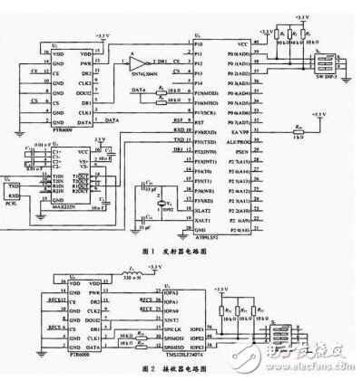
Since the serial port of the PC uses the RS 232 level, and the wireless communication module PTR6000 and the single chip AT89LS52 both use the TTL/CMOS level, level conversion is required. This system uses MAX232 chip, which is a level conversion chip, which can convert TTL to RS 232, or convert RS 232 to TTL, which can meet the communication level conversion requirements of single chip microcomputer or ordinary computer.
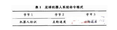
2.2 Receiver design
The receiver circuit diagram is shown in Figure 2. The receiving end is installed on each robot car. Since the control of the robot car adopts the DSP controller TMS320LF2407A, the PTR6000 wireless communication module is controlled by the TMS320LF2407A at the receiving end. Since the level standard adopted by the PTR6000 module and the MCU is the same as the TTL/CMOS level, the two are directly connected at the receiving end. After power-on, TMS320LF2407A first configures PTR6000 module, first sets CS and CE to configuration mode. TMS320LF2407A moves 120 b configuration data into PTR6 000 module through CLTR and DATA of PTR6000. After completing wireless module register configuration, TMS320LF2407A controls CS and CE starts. Receive mode. When the address of the received data coincides with the local address, the DRI output interrupt indication (active high), the DSP receives data through DATA, CLKI.
In addition, a frequency hopping dip switch is added in the design of the system, and the corresponding transmitting circuit is also provided with a frequency hopping dip switch. By adjusting the position of the dip switch to input different level combination signals, the software can jump to Corresponding channels to accommodate the need to change frequencies during the game.
3 wireless communication system software design
3.1 Wireless communication methods and protocols
Due to the limited space available for soccer robots, one-way communication is usually used. In order to achieve one-to-many communication, all broadcasts use the same communication frequency as the transmitter. Each control period wireless transmitter transmits one frame of data to all the robots of the party, and each robot reads different fields of the data frame according to its own number to obtain its own motion control instruction.
The soccer robot of this system is driven by two-wheel differential mode. Therefore, the motion control command of the robot is the set value of the left and right wheel speed of the robot. The soccer robot system command format is shown in Table 1. The robotic car on the field first receives the robot identification byte and compares it with its own logo. When the comparison is matched, it is determined that the next two bytes are instructions sent to the local machine, ready to receive; otherwise, the next two bytes of instructions are masked, waiting for the next set of instruction information.
3.2 Transceiver Software Design
The communication system software mainly has two parts: one is the RS89 receiving on the AT89LS52 and transmitting data to the PTR6000; the other is the DSP2407A receiving data from the PTR6000. Figure 3 shows the flow diagram of them.
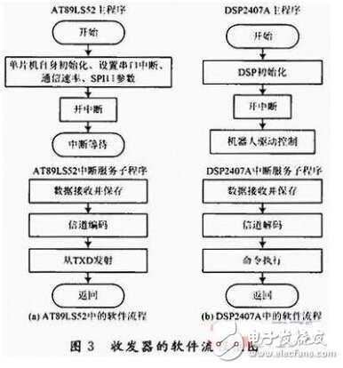
After receiving the communication command from the host computer, the AT89LS52 in the transmitter packs the received data according to the communication protocol, and then writes the data to the PTR6000 bit by programming the CLK1 pin and the DATA pin according to the timing diagram in the data sheet. It is sent to each soccer robot in broadcast form.
The receiving process of the soccer robot is executed by the DSP2407A on the robot, and each robot takes out the corresponding left and right wheel speed values ​​from the receiving buffer according to the respective set numbers. The PTR6000 at the receiving end sets the DR1 data ready pin high after receiving the same data packet as the local address. Since this pin is connected to the XINT2 interrupt pin of the DSP, the rising edge of DR1 will cause The DSP goes into the execution of the interrupt service routine and reads the received data by programming the CLK1 and DATA pins at the timing provided in the data sheet.
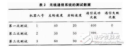
4 Experimental data and results analysis
In order to test the effect of the wireless communication subsystem. An experiment was performed here to send the same number of times (400 times) of data from the transmitter, recording the number of times the robot received the correct data (communication success) and error (communication failure). The experimental results are shown in Table 2. It can be seen that the communication success rate is high and the reliability is very good.
5 Conclusion
This paper introduces in detail the design and implementation of the soccer robot wireless communication subsystem based on the PTR6000 communication module. The experiment proves that the design makes the robot car system greatly improved in accuracy and running performance, which can meet the requirements of the soccer robot for speed, reliability and anti-interference ability.
Auto Collar
Auto Collar,Remote Dog Trainer,Best Dog Bark Control,Sky Dog Training Collar
Elite-tek Electronics Ltd , https://www.aetertek.ca