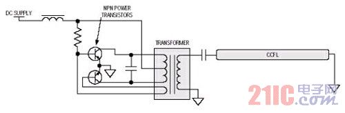
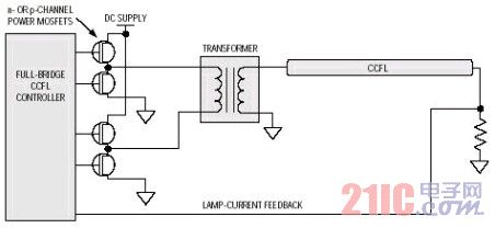
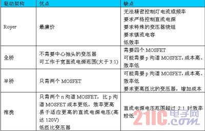
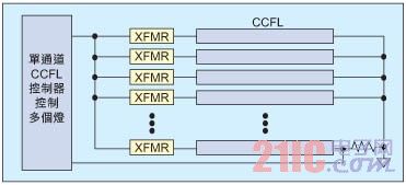
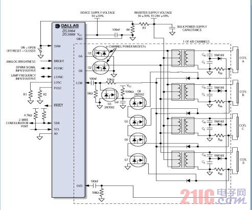
LCD TV applications can use a variety of architectures to generate the AC waveforms needed to drive CCFLs. The three key design challenges for driving multiple CCFLs are choosing the best drive architecture, multi-lamp drive, lamp frequency and pulse modulation. Optical frequency control. In this paper, four common drive architectures are compared and analyzed, and the method of solving the problem of uneven brightness and the driving frequency may interfere with the picture in the multi-lamp design is proposed, and the circuit scheme based on DS3984/DS3988 is proposed. This article refers to the address: http:// Figure 1: The Royer drive is simple but not very accurate Liquid crystal displays (LCDs) are becoming the mainstream display technology for televisions. The LCD panel is actually an electronically controlled light valve that requires a back light source to produce a visible image. LCD TVs typically use a cold cathode fluorescent lamp to provide a light source. Other backlighting technologies, such as light-emitting diodes, have also received some attention, but their use has been limited by the high cost. Since LCD TVs are consumer products, the overriding design considerations are costs—and of course the minimum performance requirements must be met. The CCFL converter that drives the backlight does not significantly shorten the life of the lamp. In addition, safety is a factor that must be considered due to the high voltage drive. In LCD TV applications, the three key design challenges to drive multiple CCFLs are: picking the best drive architecture; multi-lamp drive; strict control of lamp frequency and pulse dimming frequency. Figure 2: Full-bridge drivers are well suited for a wide range of DC power supplies. 1 Pick the best drive architecture A variety of architectures can be used to generate the AC waveforms needed to drive the CCFL, including Royer (self-oscillating), half-bridge, full-bridge, and push-pull. Table 1 summarizes the advantages and disadvantages of each of these four architectures in detail. 1.1 Royer architecture The best application of the Royer architecture (Figure 1) is in designs that do not require tight control of lamp frequency and brightness. Since the Royer architecture is a self-oscillating design, it is difficult to strictly control the lamp frequency and lamp current due to the variation of component parameters, and both of them directly affect the brightness of the lamp. Therefore, the Royer architecture is rarely used in LCD TVs, although it is the cheapest of the four architectures described in this article. 1.2 Full Bridge Architecture The full-bridge architecture is best suited for applications with very wide DC supply voltages (Figure 2), which is why almost all notebook PCs use a full-bridge approach. In notebooks, the converter's DC power comes directly from the system's main DC power supply, which typically ranges from 7V (low battery voltage) to 21V (AC adapter). Some full-bridge solutions require p-channel MOSFETs, which are more expensive than n-channel MOSFETs. In addition, p-channel MOSFETs are less efficient due to the inherently high on-resistance. 1.3 Half Bridge Architecture Figure 3: Half-bridge driver uses two fewer MOSFETs than full-bridge driver The biggest benefit of a half-bridge architecture over a full bridge is that it uses less than two MOSFETs per channel (Figure 3). However, it requires a higher ratio transformer, which increases the cost of the transformer. Also, as with the full-bridge architecture, p-channel MOSFETs may be used in the half-bridge architecture. 1.4 Push-pull architecture Push-pull drivers have many benefits: this architecture uses only n-channel MOSFETs (Figure 4), which helps reduce cost and increase converter efficiency; it is easy to adapt to higher converter DC supply voltages; higher conversions are used For DC power supply voltage, simply select the MOSFET with the appropriate drain-source breakdown voltage. The same CCFL controller can be used regardless of the DC supply voltage of the converter. However, this is not possible with full-bridge and half-bridge architectures with n-channel MOSFETs. The biggest disadvantage of the push-pull architecture is that the converter's DC supply voltage is required to be less than 2:1. Otherwise, when the DC supply voltage is at a high level, the efficiency of the system will decrease due to the high amplitude factor of the AC waveform. This makes the push-pull architecture unsuitable for notebook computers, but is ideal for LCD TVs because the converter's DC supply voltage is typically stable to within ±20%. Figure 4: Push-pull drive is very simple and can be precisely controlled 2 multi-lamp drive CCFL has been used for many years in notebook computers, digital cameras, navigation systems, and other devices with smaller LCD screens. These types of devices typically use only one CCFL, so traditional designs use only one CCFL controller. With the advent of large-size LCD panels and the need for multiple CCFLs, it is necessary to adopt new ways to cope with this new demand. One possible way is to use a single channel CCFL controller to drive multiple lamps (Figure 5). In this manner, the CCFL controller monitors the lamp current through only one of the lamps and simultaneously drives all of the lamps in parallel with nearly the same AC waveform. However, there are several drawbacks to this approach. Figure 5: Controlling multiple lamps with a single channel CCFL controller is less than ideal due to uneven brightness and other considerations Make the display no obvious bright and dark areas. Driving all the lamps with the same waveform will result in uneven brightness due to the difference in lamp impedance. Moreover, the brightness of the CCFL varies with temperature. As the hot air rises, the light at the top of the panel will be hotter than the light at the bottom of the panel, which will also cause uneven brightness. A second disadvantage of driving multiple lamps with a single channel CCFL controller is that failure of a single lamp (eg, breakage) can cause all lamps to turn off. The third drawback is that since all the lamps are driven in parallel and the lamps are turned on and off at the same time, it is required that the converter DC power supply must use a larger capacitor to enhance the decoupling effect, which increases the cost and size of the converter. One way to solve the above problems is to use a separate CCFL controller for each lamp. However, the main drawback of this approach is the added cost of the added CCFL controller. The ideal solution for backlighting LCD panels is the multi-channel CCFL controller, which drives and monitors each lamp independently for each channel. This multi-channel CCFL controller addresses both uneven brightness and single lamp failure, reduces decoupling requirements, and is cost effective. Figure 6: The DS3984/DS3988 individually drives and monitors each lamp to provide uniform brightness for LCD TVs and PC monitors 3 Strict control of lamp and pulse dimming Since LCD TVs need to display dynamic and continuous motion pictures, it has some special requirements that are not found in static display applications such as computer monitors and notebook computers. The drive frequency of the CCFL may interfere with the picture displayed on the LCD screen. If the lamp frequency is close to a certain multiplier of the video refresh rate, a slow moving line or band will appear on the screen. This problem can be eliminated by strictly controlling the lamp frequency within ±5%. The pulse dimming frequency used to adjust the brightness of the lamp also requires the same strict control. This dimming method usually uses a pulse width modulation (PWM) signal in the frequency range of 30 Hz to 200 Hz to turn off the light in a short time to achieve the dimming purpose. Since the shutdown time is short, it is not enough to make the ionization state disappear. If the pulse dimming frequency is close to the multiplier of the vertical sync frequency, a scroll line is also generated. Similarly, the pulse dimming frequency is strictly controlled within ±5% to eliminate this problem. In addition, in some LCD TVs, in order to improve the image response of the LCD screen, a slow CCFL pulse dimming frequency is required to be synchronized with the video vertical sync frequency. Figure 7: Each channel of the DS3984/DS3988 can also drive multiple lights 4 Solutions to solve LCD TV backlight challenges The DS3984 (four-channel) and DS3988 (eight-channel) CCFL controllers address all of these design challenges mentioned in this article. These components can be configured to drive one lamp per channel (Figure 6), or multiple lamps per channel (Figure 7), giving users the flexibility to cut designs to meet their price/performance goals. Multiple DS3984/DS3988s can be easily connected in series to support any number of lights to backlight LCD TV screens. The DS3984/DS3988 features a push-pull driver architecture that enables the use of lower cost, higher efficiency n-channel MOSFETs. Higher voltages can also be used for the converter DC supply voltage. Separate lamp control and monitoring provides uniform brightness and reduces the total number of components in the converter. When using a separate lamp control, if one of the lamps fails, only the failed lamp will stop working, and the other lamps will continue to work and will not be affected. The lamp frequency and pulse dimming frequency produced by the on-chip oscillator are strictly limited to ±5% level, eliminating the effects on the displayed image and can also be synchronized to an external clock source. Table 1: Comparison of CCFL Driver Architecture 5 cold cathode fluorescent lamp A cold cathode fluorescent lamp (CCFL) is a long, thin, sealed glass tube filled with an inert gas. When a high voltage is applied to the tube, the gas is ionized to produce ultraviolet (UV) light. Ultraviolet rays are applied to the fluorescent material coated on the inner wall to excite it to emit visible light. CCFL has many advantages, including: it is an excellent white light source; low cost; high efficiency (ratio of light output to input electric power); long life (>25 thousand hours); stable, certain working condition; easy to adjust brightness; light. CCFLs have some special features that must be carefully considered to maximize their efficiency, longevity and usability. However, these features present some special design challenges. For example, to maximize the life of the lamp, an AC waveform is required to drive the CCFL. Any DC component causes a portion of the gas to collect at one end of the tube, creating an irreversible light gradient that causes one end of the tube to be brighter than the other. In addition, in order to maximize its efficiency (the ratio of light output to input electrical power), it is necessary to drive the lamp with a waveform that is nearly sinusoidal. Therefore, CCFLs typically require a DC-AC converter to convert the DC supply voltage into an AC waveform from 40kHz to 80kHz, typically operating from 500VRMS to 1000VRMS. The lights in the LCD televisions are equally spaced across the entire LCD backplane to provide optimum light distribution. It is important that all lights work at the same brightness. Although a diffuser is arranged between the CCFL tube and the LCD panel to assist in evenly distributing the backlight, the uneven brightness of the tube is still easily noticeable and affects the image quality of the television. Depending on the size of the LCD panel, the number of CCFL lamps used may be as many as 30 or even 40.
Coupletech
Co., Ltd. Supply CW Laser models for medical instruments and scientific
research, consists of UV laser GN-355, Low noise blue laser GL-473, Low noise green laser DL-532nm, Signal mode
green laser CS-532, Sodium Yellow Laser GL-556, Light yellow laser GL-561,
Orange yellow laser GL-593 and Infrared laser GL-1064, and these laser models cover
a wide range of wavelengths: 355nm, 473nm, 532nm, 556nm, 561nm, 593nm, 1064nm,
and son. The application of CW laser models is for Fluorescence stimulated for
biological medical instruments, Interferometry, laser hologragh, flow
cytometry, physical instruments, scientific research and so on. The average output power is
10 mW ~ 2000 mW, beam diameter at the aperture is ~ 1.5mm. Besides, single mode fiber coupled or customized is optional.
Diode Pumped CW,Diode Pumped Solid State Laser,Solid State Laser Diode Coupletech Co., Ltd. , https://www.coupletech.com