Abstract: Automobiles should analyze the test data of each part before finalizing. At present, many sensors in automobiles are directly connected to data collectors and car batteries by wires, and a large number of wires will directly affect the test environment. Based on this, a new regulated power supply and communication subsystem was designed to replace the wires, to minimize the impact of these wires on the test environment, and to improve the authenticity of the vehicle environmental monitoring data to improve driving safety and comfort. This article refers to the address: http:// The Shielded Cable is a cable that is resistant to external electromagnetic interference formed by a transmission cable plus a shield. Shielded Cable Shielded Cable,Shielded Usb Cable,Double Shielded Ethernet Cable,Control Signal Cable Jiangsu QiSheng Cable Co., Ltd. , https://www.shuaihe-cable.com
Key words: wireless sensor; regulated power supply; communication subsystem
0 Introduction Radio frequency technology (RF) is commonly used in car driving and vehicle diagnostics. In accordance with international standards, the technical application of all vehicles must be thoroughly tested, and these tests are based on reasonable empirical experiments involving the collection of sensing data. Therefore, in the automotive industry, the development of wireless sensor networks has evolved with the development of typical sensors and RF equipment. For automotive test environments, wireless sensors have three advantages: first, small size, wireless sensors do not require cable ports; second, saving time, wireless sensors save time connecting all sensors to power and data lines, so wireless The sensor can be deployed more quickly and easily, which improves the spatial resolution of the sensed data and improves the fault tolerance of the sensor network. The third is to ask for safety during the driving test period. The number of data lines entering the cockpit is limited.
The specific structure of this paper is as follows: The second part gives the hardware design of wireless sensor; the third part gives the wireless sensor network and communication protocol; the fourth part mainly discusses the use cycle of wireless sensor network; Design situation.
1 Wireless sensor structure hardware design
1.1 Wireless Sensor Architecture The wireless sensor architecture consists of a power supply unit, a sensing module, a wireless communication module, and a microcontroller. The hardware design structure is shown in Figure 1. 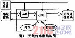
1.2 Power Supply Units Wireless sensors typically operate from 3.0 V to 3.6 V. The power supply design incorporates the TLFA274 regulator (shown in Figure 2), which can convert voltages from 3 V to 40 V, such as small batteries or car batteries that are commonly used, which brings great convenience to users. 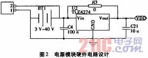
1.3 Sensing Module In order to minimize the consumption of power, the sensing module (shown in Figure 3) is powered on before the measurement, and then turned off immediately (fast switching does not affect the device). 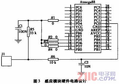
1.4 Wireless Communication Module Due to the differences in different brands of vehicles, the uncertainty of the radio frequency (RF) operating environment is caused. The wireless communication module must meet two basic design criteria: first, multi-band communication, select low-power radio frequency (RF) chips, ie 433/868/915 MHz band transceiver nRF905 and 2.4 GHz band nRF2401 transceiver Second, two antennas are available (as shown in Figure 4), PCB (simple, low power, but difficult to adjust) and external antenna (as opposed to PCB). Switching between different RF bands and antennas to ensure smooth communication, especially in vehicles with thick metal baffles between the engine compartment and the cockpit. 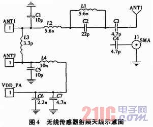
1.5 The microcontroller selects the Atmel ATmega88 for the microcontroller chip. Because of its low power consumption and fast conversion between standby mode and active mode, the wireless sensor can measure and transmit data in a very short time. It has a built-in brownout detection circuit that can be used to alert the user if the sensor network battery needs to be replaced. It also has a built-in A/D converter that converts the sensor's analog signal into a digital signal with a 10-digit value ( Zero represents 0 V, 210-1 represents the supply voltage and the maximum possible voltage).
The above just illustrates the design of a single wireless sensor. However, in an actual automotive test environment, it is also necessary to consider how many sensors are working at the same time, and how much data is needed to be transmitted.
2 Wireless sensor network Data communication for wireless sensors will use the time division multiple access communication protocol. Using Time Division Multiple Access (TDMA) means that only useful data can be transmitted and received in communication mode (higher power), so the wireless sensor is in instant messaging mode at all times. We assume a wireless sensor (master) as a constant data receiver (star topology network), and the wireless sensor is powered by a car battery (so there is no need to consider the power problem of the main wireless sensor), in addition to the role of the central processor, When all the sub-radio sensors start transmitting data, the main wireless sensor will synchronously return a special request message to the sub-radio sensor.
Two transceivers 240-bit RF data packets, using fifteen 16-bit data packets (3 bits are assigned to a 5-channel A/D converter, 10 bits are assigned to sensed data, and 3 bits are left). A window time of 10 ms is sufficient for the receiver to process a single packet, and the minimum TDMA is also 5 ms apart.
Let's calculate the maximum number of wireless sensors that can be loaded on this network, that is, the value that a TDMA network can support.
Definition: NP = data bit number in the data packet = 240; MB = measurement size (number of bits) = 16; SIl = sampling time interval (user-defined unit: second); SN = number of sensors (user-defined unit: second TT=The minimum time required for each transceiver = 5ms when using the TDMA protocol; MT = the minimum time required for the MCU to process each packet = 10ms.
Based on the above definitions, the following data can be calculated as:
Sp = number of sample packages = ![]() =15; TA = average transmission time interval; TM = average window time (in milliseconds) for each primary sensor to transmit and process under the TDMA protocol;
=15; TA = average transmission time interval; TM = average window time (in milliseconds) for each primary sensor to transmit and process under the TDMA protocol;
The sensor will send a data packet every 15 samples at the sampling interval rate. The average transmission time interval is such that TA=SP*SI.
If each TA sensor transmits a packet, each sensor can obtain a time-multiplexed time window. In order to accurately calculate the size of the time slot, the interval must be divided by the number of nodes in the network. The conversion of 1 000 to milliseconds is as follows: 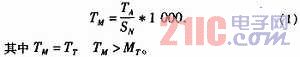
The maximum number of wireless sensors that a wireless sensor network can support depends on the time interval (SI) being sampled. Once the appropriate time interval is selected (based on the rate of change of the input), the number of nodes and the number of TDMA slots are determined using equation (1).
Using the temperature sensor as the sensor, if a sampling interval of 1 s is required, the maximum number of nodes that the master node can handle is 1 400 (TM of 10.714 ms). The master node has reached 10 ms, as shown in Figure 5(b). . 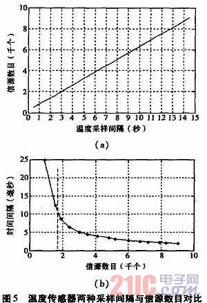
In this section, the transmission protocol of the wireless sensor is studied and it is shown that the design can achieve relatively high spatial resolution (cars larger than 1 000 node scale). However, if the sensor consumes too much power, it will need to replace thousands of batteries periodically, which in effect limits the spatial resolution. Therefore, this requires consideration of the life cycle of the wireless sensor network.
3 Sensor network life cycle The three main modules of wireless sensor consumption are: sensor module, wireless communication module and microcontroller module, as shown in Table 1. These three modules mainly have two modes of operation: shutdown mode and working mode. The power consumption of each module is analyzed in both modes, as well as the total consumption. 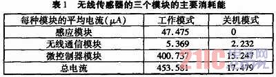
In addition, using a standard of 500 mAh battery, this is the current required by the supply can not be reduced, to deduct 20% of the theoretical amount. Therefore, to calculate the average life (hours), the formula is: 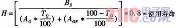
BS=Battery power supply for one hour = 500 mAh; AO = sensor current amount in working mode = 453.581μA;
AOF=sensor current amount in shutdown mode=17.479μA; TO=time rate (%) of sensor in working mode.
4 Conclusion This article details the hardware design of a single wireless sensor and wireless sensor network transmission protocol, which can quickly and easily collect real data in a large number of automotive test environments. This design is flexible enough to use multiple bandwidths, antennas, power supplies, and sensor types. The wireless transmission method is used to test the condition of each part of the vehicle, which greatly improves the influence of the test equipment on the real environment and makes the test data more realistic. However, in the actual test environment, the wireless star network topology is often used, and there are multiple RF transmitting devices, which may cause intermodulation distortion. Wireless signals are likely to propagate multiple times around the vehicle (reflection, diffraction, etc.), causing noise to occur. These issues will be subject to further experimentation and debugging. Since the power consumption of the external oscillator is relatively large, a relatively accurate internal oscillator will be used internally; due to the high clock error rate, resynchronization must be performed periodically to achieve the desired communication performance.
Most of the shielding layers of such cables are woven into a mesh metal wire or a metal film, and there are many different ways of single shielding and multiple shielding. Single shielding refers to a single shielding mesh or shielding film in which one or more wires can be wrapped. The multi-shielding method is a plurality of shielding nets, and the shielding films are all in one cable. Some are used to isolate electromagnetic interference between wires, and some are double-layer shields used to enhance the shielding effect. The mechanism of the shielding is to ground the shield to isolate the externally induced inductive voltage of the conductor.