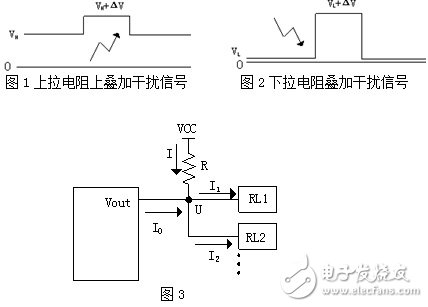
On various technical data, some technical specifications write that "useless pins are not allowed to be left floating, and pull-up or pull-down resistors must be connected to provide a certain working state." This formulation is basically correct, but not all right. The details are explained below. There are two starting points for the pull-down resistor design on the pin: One is that under normal working or single fault conditions, the pins should not be in an indeterminate state, such as the pins hanging after the connectors fall off; Second, from the perspective of power consumption, in the long-term pin wait state, the resistance of the pin port should not consume too much current, especially for battery-powered devices. From the perspective of immunity, the signal port is preferably a pull-up resistor. When the pull-up resistor is in the standby state, the source input is always in a high-impedance state. If there is no pull-up resistor or pull-down resistor, the input conductor exhibits an antenna effect. Once the pin is subjected to radiation interference, the pin input state is easily induced. Variety. Therefore, this resistance is definitely added. The next question is whether to add or pull down. If a pull-down is added, the input will be low in the normal state, but after the radiation interference comes in, it will be discharged to the ground through the pull-down resistor, and a jump from Low-High will occur, causing a false trigger. Equivalent to a jealousy, you gave him 100,000 yuan, and his lifestyle will change from poor to rich. However, if a pull-up resistor is added, in normal state, the input behaves as a high level. After the radiation interference comes in, if it is low, it does not matter. The pull-up resistor clamps the input terminal at a high level. If the radiation interference is strong, it exceeds With the level of Vcc, the high-level interference on the wire will be discharged to Vcc through the pull-up resistor. No matter how the interference occurs, only the High-Higher change will occur, and no false trigger will occur. Equivalent to a person who was originally a rich man, you gave him 100,000 yuan, his lifestyle will not change. 1 and 2 are diagrams showing levels in an interference state. When the low level in FIG. 2 is changed from VL to VL+ΔV, a transition from a low level to a high level occurs, which may cause a malfunction of the subsequent stage circuit. The next question is, after using the pull-up resistor, is it possible to pick up the pull-up resistor? The answer is of course "no". (Figure 3) When the front pole outputs a high level, Vout outputs current and U is high. There are two situations: A, when I0 >= I1 + I2 In this case, the two loads RL1 and RL2 do not take current through R, so the R resistance is not required, usually 4.7 KΩ. B, when I0 I0 +I= I1 + I2 U=VCC-IR U>=VHmin Calculated from the above three formulas, R<=(VCC- VHmin)/I Among them, I0, I1, I2 can be found from the datasheet, I can be found, VHmin can also be found. When the current Vout output is low, each pin is sinking current, then: I'= I1' + I2' +I0' U' =VCC-I' R U' <=VLmax The above three formulas can be obtained: R>=(VCC- VLmax)/I' The upper limit value and the lower limit value of R are calculated from the above two formulas, and a value closer to the intermediate state may be taken therefrom. Note that if the number of loads is variable, it should be calculated according to the worst case. The upper limit should be calculated according to the maximum load, and the lower limit should be calculated according to the least load. Another option is based on power consumption considerations. The frequency or time ratio of the output signal state is selected according to the actual application of the circuit. If the signal Vout is at a low level for a long time, the pull-down resistor should be selected; if it is at a high level for a long time, the pull-up resistor should be selected. In order to have a small quiescent current. “Design is always the art of compromise and trade-offs.†As for the choice of the solution, the technical decision of the designer is still very important. The charm of circuit design is also here.
Desktop Type Power Adapter, small size switch with12VDC,12W,24W,36W,60W
Features:
Wide input range: 100-240V, 50/60Hz.
Full current,all using brand new capacitors
Glass fiber board (FR-4)
Special shield housing design for cooling.
Plastic housing use ultrasonic process, it is No need any screw.
4 times aging test
100% Enough Power,
High efficiency 85%.
3 years warranty
Product application:
Application to CCTV, Access control,Alarm System.
Desktop Type Power Adapter Desktop Type Power Adapter,Power Supply Plug Type, Power Adaptor,Power Inverter Guangdong Steady Technology Co.LTD , https://www.steadysmps.com
Protections:short circuit, over current, overload.
Customized Ac Plug, EU,UK,USA,AU Plug is available