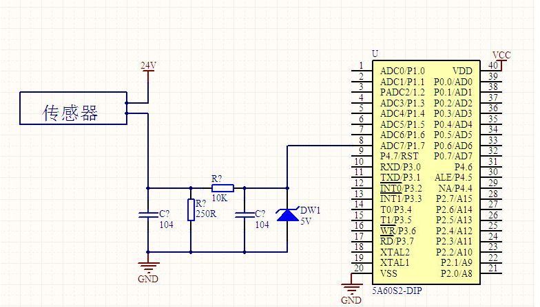
The 4-20mA. DC (1-5V.DC) signal system is an analog signal transmission standard used by the International Electrotechnical Commission (IEC) process control system. Our country also adopts this international standard signal system, the instrument transmission signal uses 4-20mA.DC, the receiving signal uses 1-5V.DC, namely uses the electric current transmission, the voltage receives the signal system. The general instrumentation signal current is 4-20mA, which means the minimum current is 4mA and the maximum current is 20mA. When the signal is transmitted, because the wire also has resistance, if the voltage transmission will produce a certain pressure drop in the wire, then the signal of the receiving end will produce a certain error, so the current signal is generally used as a standard transmission transmitter. First, what is the 4~20mA.DC (1~5V.DC) signal system? The 4~20mA.DC (1~5V.DC) signal system is the International Electrotechnical Commission (IEC): analog signal standard for process control systems. Our country adopts this international standard signal system from DDZ-III type electric instrumentation, the instrument transmission signal adopts 4~20mA.DC, the contact signal adopts 1~5V.DC, namely adopt the signal system of electric current transmission, voltage to receive. 4~20mA current loop working principle: In the industrial field, using an instrumentation amplifier to complete the signal conditioning and long-term transmission, will produce the following problems: First, because the transmitted signal is a voltage signal, the transmission line will be disturbed by noise; Second, the distribution resistance of the transmission line will produce Voltage drop; Third, how to provide the operating voltage of the instrumentation amplifier in the field is also a problem. In order to solve the above problem and avoid the influence of related noise, we use current to transmit the signal because the current is not sensitive to noise. The current loop of 4-20mA is the zero signal represented by 4mA, the full scale of the signal is represented by 20mA, and the signal higher than 20mA below 4mA is used for the alarm of various faults. Second, 4 ~ 20mA.DC (1 ~ 5V.DC) signal system advantages? The field instrument can realize two-wire system. The so-called two-wire system, ie, power supply and load, are connected in series and has a common point. The signal connection and power supply before field transmitter and control room instrument use only two wires. Because the starting point current of the signal is 4mA.DC, it provides the quiescent operating current for the transmitter. At the same time, the instrument's electrical zero is 4mA.DC, which does not coincide with the mechanical zero. This "living zero" is helpful to identify faults such as power failure and disconnection. . Moreover, the two-wire system also facilitates the use of safety barriers, which is conducive to safety and explosion protection. The control room instrument adopts voltage parallel signal transmission. There is a common terminal between the instruments that belong to the same control system, which is convenient for detecting instruments, regulating instruments, computers and alarm devices, and is convenient for wiring. The reason why the contact signal between the field instrument and the control room instrument adopts 4~20mA.DC is because the distance between the site and the control room is far, and the resistance of the connection wire is relatively large. If the voltage signal is used for remote transmission, it is better than the wire. The resistance of the resistor and the input resistance of the receiving instrument will cause a large error, and the constant current signal will be used as the remote transmission. As long as the transmission loop does not branch, the current in the loop will not change with the length of the wire, thus ensuring the The accuracy of the transmission. The communication signal between the control room instruments uses 1~5V DC. The reason is: In order to facilitate multiple instruments to receive the same signal together, it is beneficial to the wiring and forms a variety of complex control systems. If the current source is used as the contact signal, when multiple instruments receive the same signal together, their input resistance must be connected in series. This will cause the maximum load resistance to exceed the load capacity of the transmitter and the negative terminal potential of each receiver. Differently, interference will be introduced and a single centralized power supply cannot be achieved. Using a voltage source signal, the current signal used to communicate with the field instrument must be converted to a voltage signal. The simplest method is to connect a 250Ω standard resistor in series with the current transfer circuit to convert 4~20mA.DC to 1~5V. .DC, which is usually done by distributors. Third, why the transmitter selects 4~20mA.DC for transmission signal? 1. First, consider the safety of field applications The focus of safety is based on the explosion-proof safety spark instrument, and on the premise of controlling the instrument energy, the static and dynamic power consumption to maintain the normal operation of the instrument is reduced to the minimum. Transmitters outputting 4~20mA.DC standard signals usually use 24V.DC as the power supply voltage. The main reason for using DC voltage is that without the need for large-capacity capacitors and inductors, only transmitters and control room instruments need to be considered. The distributed capacitance and inductance of the connecting wire, such as a 2mm2 wire, has a distributed capacitance of about 0.05μ/km; for a single wire, the inductance is about 0.4mH/km; it is much lower than the value of the detonated hydrogen, and obviously this is very favorable for explosion protection. 2. Current source for signal transmission is better than voltage source Because the distance between the site and the control room is far, and the resistance of the connecting wire is large, if the voltage source signal is used for remote transmission, a large error will occur due to the voltage resistance of the wire and the input resistance of the receiving instrument, if the current is used. The source signal acts as a remote transmission. As long as no branch occurs in the transmission loop, the current in the loop will not change with the length of the wire, thus ensuring the accuracy of the transmission. 3, the reason why the signal maximum current selects 20mA The choice of maximum current 20mA is based on considerations of safety, utility, power consumption, and cost. Safety spark instruments can only use low voltage, low current, 4~20mA current and 24V.DC are also safe for flammable hydrogen. For 24V.DC hydrogen detonation current is 200mA, far more than 20mA, in addition to comprehensive consideration of production The distance between the on-site instruments, the load factors, etc., as well as the power consumption and cost, the requirements on the electronic components, and the power supply requirements. 4, the origin of the signal selection 4mA reason The transmitter with 4-20mA output is mostly in two-wire system. The two-wire system, ie, power supply and load, are connected in series. There is a common point, and the signal connection and power supply between the field transmitter and the control room instrument are only two. Wires. Why is the starting signal not 0mA? This is based on two points: First, the transmitter circuit will not work without quiescent current, the signal starting current 4mA.DC, does not coincide with the mechanical zero, this "living zero" is conducive to identify faults such as power off and disconnection. Fourth, the origin of 4~20mA sensor? The reason why the current signal is used is that it is not susceptible to interference, and the current source has infinite internal resistance. The resistance of the wire in series in the loop does not affect the accuracy, and it can be transmitted several hundred meters in an ordinary twisted pair. The reason for using current signals is not easily disturbed, because the noise voltage in the industrial field may reach several V, but the noise power is weak, so the noise current is usually less than the nA level, so the error caused by the 4-20mA transmission is very high. Small; current source internal resistance tends to infinity, wire resistance in series in the loop does not affect the accuracy, so can be transmitted hundreds of meters in the ordinary twisted pair; due to the current source of large internal resistance and constant current output, at the receiving end we only need Place a 250 ohm to ground resistor to obtain a voltage of 0-5V. The benefit of a low input impedance receiver is that the nA input current noise produces only very weak voltage noise. The upper limit of 20mA is due to the explosion-proof requirement: the spark energy caused by the on-off of the 20mA current is not enough to ignite the gas. The reason why the lower limit does not take 0 mA is to detect the disconnection: Normal operation will not be lower than 4 mA. When the transmission line is disconnected due to a fault, the loop current will drop to zero. Always take 2mA as the disconnection alarm value. The current-type transmitter converts the physical quantity into a 4-20mA current output, which inevitably requires an external power supply to supply it. The most typical is the transmitter requires two power lines, plus two current output lines, a total of four lines, called four-wire transmitter. Of course, the current output can be shared with the power supply for a common line of VCC or GND, which saves one line and is called a three-wire transmitter. In fact, you may notice that the 4-20mA current itself can power the transmitter. Transmitter in the circuit is equivalent to a special load, the special point is that the power consumption of the transmitter varies between 4~20mA according to the sensor output. The display meter only needs to be in the circuit. This transmitter requires only two external wires and is therefore called a two-wire transmitter. The lower limit of the industrial current loop is 4mA, so the transmitter has at least 4mA of power within the range. Therefore, the 4-20mA signal output is generally not susceptible to interference and safe and reliable, so the industry is generally used two-wire 4-20mA power output signal. But in order to better deal with the sensor signal, there are still more other forms of output signal: 3.33MV/V; 2MV/V; 0-5V; 0-10V and so on. A simple circuit diagram with a 4 to 20mA transfer voltage signal is attached: This figure uses a 250 ohm resistor to convert a 4 to 20 mA current signal to a 1 to 5 V voltage signal, and then uses an RC filter plus a diode (forgive me the analog circuit is not good, do not know what it means) received AD conversion pins of the microcontroller. Miniature Current Transformer,Micro Precision Current Transformer,Miniature Transformer With Aperture,Miniature Precision Current Transformer Zibo Tongyue Electronics Co., Ltd , https://www.tongyueelectron.com