Abstract: Combining the principle of video image reception and its application in SGJ-5 video optical receiver, a peak-type AGC circuit is introduced, its working principle and control method are analyzed, and its design and implementation process are detailed.
Keywords: Automatic Gain Control Circuit Video
1 Introduction In industrial video transmission systems, due to the influence of different receiving environments or external interference and aging of the device, the strength of the received signal may vary greatly. When the signal is weak, the contrast of the image will become smaller, the definition is poor and the synchronization is unstable, and the image cannot be imaged. A strong signal will cause the post-amplifier to enter the saturation and cut-off regions, causing severe distortion of the signal, and will also cut off the sync pulse, resulting in no good image. In the monitoring system related to safety production, high-quality and stable video image signals are especially important for the production of enterprises.
To this end, this article introduces a peak-type video automatic gain control (AutomaTIc Gain Control, AGC) circuit. According to the characteristics of the maximum amplitude of the sync head in the video signal, it takes the peak value of the sync head as the control voltage of the amplifier gain, has nothing to do with the content of the transmitted image, and can suppress the low-frequency interference mixed in the video signal.
2 AGC circuit working principle and control method
2.1 Working Principle In the SGJ-5 video optical receiver, the block diagram of the AGC system is shown in Figure 1.
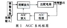
Through the optical / electrical conversion circuit, the video signal transmitted from the optical fiber is converted into an electrical signal, and after adjusting the voltage division, it enters the video amplification circuit. Its AGC feedback loop obtains the video signal from the output and undergoes detection and rectification to make it follow the video. The strength of the signal varies with the DC control voltage. This voltage feedback controls the DC operating point of the video amplifier transistor, thereby changing its gain to achieve the purpose of stable output.
The AGC system is mainly composed of circuits such as video amplification, AGC detection, and AGC amplification. It is a closed-loop amplitude feedback control system.
Among them, the AGC control circuit is composed of AGC detection, AGC amplification and other circuits. The AGC detection detects the video signal representing the strength of the signal to obtain a DC voltage proportional to the strength of the input signal. This voltage is the AGC control voltage.
2.2 Control methods There are two control methods for the AGC control circuit, one is forward AGC and the other is reverse AGC. The characteristic of positive AGC is that when the input signal ui increases, the AGC control voltage also increases, while the gain K of the amplifier decreases, that is Ui ↑ → UAGC ↑ → K ↓. Obviously, the characteristic of reverse AGC is Ui ↑ → UAGC ↓ → K ↓.
When the reverse AGC works, the signal increases, and the current at the operating point of the transistor decreases instead, so that the dynamic range enters the cut-off region, making the AGC circuit AGC function invalid. Therefore, the AGC circuit proposed in this paper uses positive AGC. Amplifiers for forward AGC must use dedicated transistors with AGC function, and their output characteristic curve is broom-shaped. When Uce is a certain value, the β value of the tube changes significantly with the operating point IC, and the relationship between its transistor current and gain is shown in Figure 2.

3 Circuit analysis The AGC voltage is taken from the video output, reflecting the strength and weakness of the video signal, but it is not expected to be affected by the content of the video signal. For this reason, the system uses a peak-type AGC circuit. Compared with the average type AGC circuit and the keyed type AGC circuit, the AGC voltage of the peak type AGC circuit changes with the peak value of the video signal (that is, the sync head pulse), which is only related to the strength of the external signal and has nothing to do with the content of the image. The influence of the image content on the AGC voltage is avoided. Its AGC circuit is shown as in Fig. 3.
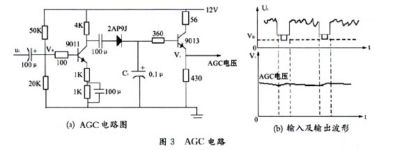
Among them, the transistor 9011 is an AGC detection tube, 2AP9J is a detection diode, and C1 is a voltage holding capacitor. The AGC voltage is output from the emitter of 9013, which improves the load capacity of the output voltage. A positive image signal is added to the base of 9011. After 9011 reverse-phase amplification, the positive sync head acts on the positive electrode of 2AP9J to perform peak detection and charge C1. The charging time constant is very small. When the sync header passes, the 2AP9J ends. At this time, the voltage charged by C1 is equivalent to the amplitude of the sync tip. The voltage on C1 is discharged through the input impedance of the emitter follower 9013. Since the input impedance of the emitter follower is large, it can reach 100K, so the discharge is slow. When C1 = 0.1μF, the discharge time constant is 104μs, which is much larger than the line synchronization period. Therefore, the voltage on C1 can be regarded as maintained at the peak value, which is output through the emitter follower as the control voltage of AGC. The stronger the video signal, the higher the control voltage. As a result of the AGC control, the gain of the amplifier is reduced and the amplitude of the image signal is reduced. Finally, the image signal output by the video is kept within a certain peak-to-peak range.
4 conclusions The peak type AGC circuit that this text introduces, its control voltage has nothing to do with the content of the picture, it is only related to the amplitude of the sync head. The capacitor charging time constant is very small, when the synchronization head arrives, the capacitor can quickly reach the voltage amplitude of the synchronization head. The discharge time constant is in the order of milliseconds, which can keep up with the changing speed of the low-frequency interference signal mixed in the video signal, has an anti-modulation effect, and can suppress the low-frequency interference.
However, there is also a shortcoming. Because the charging time constant of the AGC circuit is very small, the working state of the interference signal AGC mixed with the level of the sync head in the video signal is greatly affected. It charges the capacitor C1 to the peak of the interference signal, the transistor gain drops sharply, which affects the image contrast. At the same time, due to the relatively large discharge time constant, the C1 voltage cannot return to the normal state within a few line synchronization periods. Receive images stably.
references
1 Zhou Guiyou, etc. Principles of color TV. Nanjing: Southeast University Press, 1992
2 Chen Xianyao and others. Principles of color TV receivers. Beijing: Higher Education Press, 1993
3 Gao Yuanhuan. IC manual for video signal processing. Beijing: Tsinghua University Press, 1996
4 Diao Ming. Principles of TV receivers. Beijing: Xueyuan Press, 1999
In-ear earphones, also known as ear canal earphones, are used inside the human hearing organs and, according to their design, sealing the user's ear canal. In-ear earphone is inserted into the ear canal with a gel plug, to obtain better airtightness, on the basis of the ordinary earphone, which greatly increasing the performance of in-ear earphone.
Advantages:
1: Reduce the interference of external noise on music.
2: Provide a closed environment that greatly reduces leakage. From a practical point of view - in a noisy environment,you can enjoy music with a relatively low volume.
3:Increase the low frequency texture and volume.
4:Adding to the performance of the music details.
The catheter of these headphones are connected to the earmuffs into the front half of the ear canal to create a sealed listening environment. And many high-end in-ear earphones even custom-made eardrums for the best comfort and perfect sound insulation.

Earbuds Earphones
Earbuds Earphones,Tws Earphone,Voice Changer Earphone,In Ear Headphones With Mic
Shenzhen Linx Technology Co., Ltd. , https://www.linxheadphone.com