Park First Aid Circuit-Park-Aid
Parts:
R1_____________10K 1 / 4W Resistor
R2, R5, R6, R9 _____ 1K 1 / 4W Resistors
R3_____________33R 1 / 4W Resistor
R4, R11 __________ 1M 1 / 4W Resistors
R7______________4K7 1 / 4W Resistor
R8______________1K5 1 / 4W Resistor
R10, R12-R14 _____ 1K 1 / 4W Resistors
C1, C4 ___________ 1Î…F 63V ElectrolyTIc or Polyester Capacitors
C2_____________47pF 63V Ceramic Capacitor
C3, C5 _________ 100Î…F 25V ElectrolyTIc Capacitors
D1 _____________ Infra-red LED
D2 _____________ Infra-red Photo Diode (see Notes)
D3, D4________1N4148 75V 150mA Diodes
D5-7 ___________ LEDs (Any color and size)
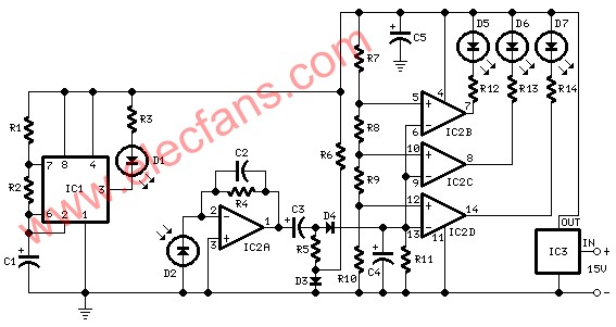
IC1_____________555 TImer IC
IC2___________LM324 Low Power Quad Op-amp
IC3____________7812 12V 1A PosiTIve voltage regulator IC
Device purpose:
This circuit was designed as an aid in parking the car near the garage wall when backing up. LED D7 illuminates when bumper-wall distance is about 20 cm., D7 + D6 illuminate at about 10 cm. And D7 + D6 + D5 at about 6 cm. In this manner you are prompt when approaching too close to the wall.
All distances mentioned before can vary, depending on infra-red transmitting and receiving LEDs used and are mostly affected by the color of the reflecting surface. Black surfaces lower greatly the device's sensitivity.
Obviously, you can use this circuit in other applications like liquids level detection, proximity devices etc.
Circuit operation:
IC1 forms an oscillator driving the infra-red LED by means of 0.8mSec. Pulses at 120Hz frequency and about 300mA peak current. D1 & D2 are placed facing the car on the same line, a couple of centimeters apart, on a short breadboard strip fastened to the wall. D2 picks-up the infra-red beam generated by D1 and reflected by the surface placed in front of it. The signal is amplified by IC2A and peak detected by D4 & C4. Diode D3, with R5 & R6, compensate for the forward diode drop of D4. A DC voltage proportional to the distance of the reflecting object and D1 & D2 feeds the inverting inputs of three voltage comparators. These comparators switch on and off the LEDs, referring to voltages at their non-inverting inputs set by the voltage divider resistor chain R7-R10.
Notes:
Power supply must be regulated (hence the use of IC3) for precise reference voltages. The circuit can be fed by a commercial wall plug-in power supply, having a DC output voltage in the range 12-24V.
Current drawing: LEDs off 40mA; all LEDs on 60mA @ 12V DC supply.
The infra-red Photo Diode D2, should be of the type incorporating an optical sunlight filter: these components appear in black plastic cases. Some of them resemble TO92 transistors: in this case, please note that the sensitive surface is the curved, not the flat one.
Avoid sun or artificial light hitting directly D1 & D2.
If your car has black bumpers, you can line-up the infra-red diodes with the (mostly white) license or number plate.
It's wiser to place all the circuitry near the infra-red LEDs in a small box. The 3 signaling LEDs can be placed far from the main box at an height making them well visible by the car driver.
The best setup is obtained bringing D2 nearer to D1 (without a reflecting object) until D5 illuminates; then moving it a bit until D5 is clearly off. Usually D1-D2 optimum distance lies in the range 1.5-3 cm.
If you are needing a simpler circuit of this kind driving a LED or a relay, click Infra-red Level Detector
Kara offers a range of Rotary Switches.Ranging from 5 to 9 poles,15VA to 25 amp,with many choices of functions,especially the switches with High-Current .Certifications include CSA, CE, and more.
This item used very in the line of cooler,with metal panel or plastic panel or only switch are all available.


Rotary Switch
Rotary Switch,Rotary Switch Knobs,Rotary Switch 6 Position,Mini Rotary Switch
Ningbo Kara Electronic Co.,Ltd. , https://www.kara-switch.com