Optimize the efficiency of microcontrollers for ultra-low power designs Whether it is consumer, industrial or medical applications, power consumption optimization is generally achieved by shortening the effective processing time and extending the processor sleep mode time. However, with the emergence of ultra-low power applications, this method has been unable to meet the requirements. Single-cell operation, charging and discharging close to the battery threshold, control requirements for motors and / or high-brightness LEDs, and reducing device size and cost have changed trends in how developers optimize power consumption. For electric toothbrushes, PMPs, remote controls, wireless sensors, and other portable and handheld devices, power management must be implemented at all levels of the system. By optimizing power consumption through efficient single-cell voltage conversion, using multiple current modes, introducing smart battery management, and applying energy-saving technologies at the application level, power consumption can be adjusted across the entire system. Efficient voltage conversion Many ultra-low power applications are moving towards a single-cell architecture to reduce device cost, size and weight. These three elements are also the key to determining the success of battery-powered portable applications. In many cases, the battery is even heavier than all other components plus PCB. In addition, standard AA or AAA batteries are usually the largest components on the PCB. The solution of reducing the power supply to a single battery is attractive because it can simplify the design of the battery holder and make the overall structure of the product more lightweight. However, the design of a single battery power supply also brings various new challenges to designers. Although the voltage range of a single battery is usually 1.2V-1.5V when fully charged, in fact, even if the battery voltage drops below 1V, there is still a lot of energy available. An MCU with a power supply voltage of 1.8V requires at least two batteries to work in series. Some applications, such as driving high-brightness LEDs with large forward voltages, require as many as 4 batteries. In order to drive the motor, LED and even the processor itself through a single battery, a regulator must be used to raise the existing voltage to an appropriate level. However, the cost of the boost regulator is almost equivalent to an MCU, and it also requires a lot of PCB space. In addition, some regulators must also be controlled by the MCU, which further increases the complexity of the design. The seamless operation of the integrated self-management boost regulator in the MCU not only avoids most of the cost and space issues caused by external regulators, but also provides higher MCU compared to using an external DC-DC converter Effect. For example, the integrated regulator ATTiny43U (see Figure 1) can boost voltages as low as 0.7V, and can discharge more than the technology supported by other types of implementation schemes near the limit of battery reserves. An integrated regulator can also achieve a relatively small reactive current (ATTIny43U's typical value is 1uA), and once there is enough voltage, it can automatically start (1.2V indicates that the battery is full or close to completion of charging). In addition, this regulator also supports all battery technologies, giving designers full freedom to choose the best battery for a particular application. The battery voltage range is 0.7V-1.8V, developers can use 1.6V alkaline batteries or silver oxide batteries, 1.5V lithium batteries, 1.4V zinc-air batteries (Zinc-Air), and 1.2V nickel-metal hydride and nickel-cadmium batteries, etc. . Boost and low current modes For many applications, the high current capability without an external drive circuit is also very important. ATTIny43U's boost regulator has a current drive capability of up to 30mA and can directly control high-brightness LEDs and small motors. Since the regulator is an integrated part of the MCU, it can be optimized for the architecture to maximize efficiency. For example, Figure 2 shows the conversion efficiency of ATtiny43U to a specific load current based on residual charge. As shown in the figure, the efficiency of high-current operation is lower than that of current-less operation. However, most high current applications do not require continuous operation in high current mode. For example, electric toothbrushes or cameras only occasionally start the motor. If its architecture is locked in high-current mode, even if only a small amount of power is required, the operating efficiency of these devices is very low; that is to say, the regulator will come with low efficiency characteristics under high-current operating conditions Provide low current. To maintain efficiency, the MCU must be able to support multiple operating modes. Therefore, when the device requires large current and strictly regulated Vcc, the MCU and regulator will work in Regulated Mode. On the other hand, when the motor or other peripherals are idle and the load current drops below 0.6mA, the regulator automatically switches to Low Current Mode to more effectively regulate power consumption. In addition, at light or no load, the converter in regulation mode will periodically reach its low duty cycle limit. By automatically switching to the low-current mode, the converter stops the conversion, the power consumption is reduced to a minimum, but at the same time remains active (see Figure 3). When the MCU is powered off or the power consumption is extremely small, the output voltage will have this change. In the main working mode, namely the Active Regulated Mode, the output voltage remains stable (3V +/- 100mV). It should also be noted that the typical conversion voltage will vary with battery energy consumption (see Figure 4). The regulator is an independent subsystem and does not require active management by the MCU. However, for designers who need to control the boost regulator more directly, certain features can be controlled using software. Since the actual efficiency depends on the application, it is meaningless to integrate all passive devices related to power regulation. For example, cost is the dominant factor in some markets, while in others, the most important driving force may be service life. Rather than being forced to use passive devices optimized for other markets, or products where all applications are satisfactory but not optimal, developers should choose passive components that provide the best balance for their applications. This can be done with only a few components (ie an inductor, two bypass capacitors and a Schottky diode). Intelligent battery management Accurate estimation of remaining energy is an important factor in maximizing TV power usage. For example, rechargeable batteries need to be closely monitored and charged within the setting range to ensure the safe use of the battery and obtain the longest possible service life. The more accurate the estimation of the remaining charge, the closer the battery can reach the limit capacity to safely charge and discharge without worrying about damage to the battery due to excessive charge and discharge. Although more precise battery charge and discharge control means that the battery has more available energy and thus longer use time, this control method lacks flexibility and may severely limit the battery technology that the processor can support. For example, batteries with different chemical properties have different safe charge and discharge voltage thresholds. If the MCU has a fixed threshold or is limited in the way of threshold configuration, it will become an obstacle for the battery technology that the MCU effectively manages. Therefore, developers may be forced to use specific batteries based on the MCU they choose, rather than choosing the most suitable battery technology. For applications where batteries must be replaced, flexibility to support rechargeable batteries is critical. The threshold of a rechargeable battery is much different from that of a disposable battery, and if it is consumed too much, it may damage its overall charging capacity. The resulting shortened usage time is very likely to be classified as a device failure rather than a battery failure. The firmware of ATtiny43U can use the built-in ADC to monitor the battery voltage and decide when to put the device into Stop Mode to completely consume the power of the disposable battery, while ensuring that the rechargeable battery can get the most on multiple charging cycles Long use time. Although automatically shutting down the processor can protect the rechargeable battery, from an application perspective, a sudden power failure may not be acceptable. For example, turning off the camera suddenly can expose the lens and make the lens vulnerable to damage. Therefore, designers can accurately estimate the remaining energy through an important power management component. For example, using the 10-bit ADC of ATtiny43U to measure the battery voltage at regular intervals can achieve the aforementioned purpose. With this method, there is an opportunity to put each device into a safe configuration before the device is turned off. High efficiency at the application level Many applications will add an MCU as the auxiliary processor of the host processor for offloading tasks such as display refresh, keyboard monitoring, small motor work, and intelligent battery management. The advantage of using an auxiliary processor is that the MCU can perform these functions with higher efficiency than the application processor. For example, an application processor that monitors the keyboard must be woken up frequently to perform tasks. And because the power consumption of the MCU in the working mode is less than that of the application processor, using the MCU to monitor the keyboard and update the display can enable the application processor to continue to sleep for a longer time, thereby saving considerable energy. Of course, processing efficiency also has a significant impact on power efficiency, because the more work an MCU can perform each cycle, the faster it will enter sleep mode. And increasing the clock frequency will increase power consumption, so the more efficient MCU architecture can support a dynamic operating frequency and execute instructions in a single cycle, and perform peripheral automation management. Ultra-low power MCUs also require multiple sleep modes. For example, a sensor application can monitor the temperature until it exceeds a threshold. If the entire MCU is in working mode during monitoring, it will consume more energy than actually needed. Supports different sleep modes, allowing developers to shut down different parts of the device to achieve better energy savings (see Table 1). There are several architectural innovations in the ATtiny43U architecture, which can be used by developers to improve the efficiency in work mode and sleep mode: Accurate power supply voltage: Although the MCU can accept a single voltage power supply, it may have multiple different internal voltages in the architecture. This design method brings low power efficiency because the dynamic power is higher than expected. If all analog peripherals, flash memory, EEPROM, and RAM work at the same voltage, the overall power consumption of the device will be reduced. Leakage current is minimized: temperature, power supply voltage and process technology all affect the leakage current. Ultra-low-power MCUs do not modify the existing architecture to enable them to operate at lower voltages, but must be designed from the ground up with the concept of power efficiency, and Atmel ’s picoPower AVR microcontroller series is an example. . Low-power undervoltage detection (Brown-Out Detection, BOD): Although zero-power undervoltage detectors do not consume power, their response speed is also very slow, it may take a full millisecond to detect the voltage below the threshold, This poses risks to the MCU. Conversely, "Sleep BOD" can detect undervoltage conditions within 2 microseconds, and the power consumption is only 20uA. Since the MCU does not need undervoltage protection in deep sleep mode, the sleep BOD can be turned off at this time, and zero power consumption is achieved. In this way, developers can achieve low power consumption and fast response at the same time. Digital Input Interrupt Register (DIDR): Multiple inputs to peripherals (such as ADCs) can increase the design flexibility of devices with small pin counts. However, when a voltage in the range of Vcc / 2 is applied, the transistor containing the input buffer will leak current. At this time, if you use a special input interrupt register and add a disable bit to each analog input, developers can individually disable the input buffer to avoid leakage. Clock gating: Clock gating technology can reduce the switching frequency of any clock domain. Any unused clock can be gated to avoid unnecessary power consumption. Power-saving registers: Although multiple sleep modes can simplify power management, they often only enable or shut down the entire peripheral section. In this way, even if only one peripheral is used, the other peripherals must also be in working condition. Power Saving Register (Power Reduction Register) allows developers to completely independently control the switch of each peripheral module. Disabling a peripheral module in working mode can reduce the total power consumption by 5-10%; in idle mode, it can save 10-20%. Flash memory sampling: The traditional flash memory design is to maintain the active state in the working mode. However, when the clock rate is low, the flash memory read time will be less than the clock cycle. Flash sampling technology is to allow the flash to sample the contents of the array at a speed of the order of 10ns, and then immediately disable it, thereby reducing the average power consumption. Fast wake-up: If the system is awakened slowly, it has to stay in working mode for a longer time to adapt to longer delays and prevent interruption of real-time event processing. In other words, the faster the MCU wakes up, the longer it stays in sleep mode. How to choose an ultra-low power / ultra-low voltage MCU When evaluating different ultra-low power MCU specifications, developers must be sober to ensure the comparison of equivalent measurement results. For example, you should consider: ? Efficiency within a certain range: The efficiency specification is usually based on the best measurement (optimum point) of the MCU rather than the result of the load current and voltage. The typical operating range of an application may place it on a lower efficiency curve. In addition, efficiency must be estimated over the entire voltage drop range of the battery. The safe operating range of the battery: Although the power consumption of the MCU may be quite small, if the voltage and temperature cannot be measured accurately enough, the battery limit may be exceeded, resulting in damage to the battery and shortened use time. Accuracy is a key factor when determining the battery energy that a device can safely use. ? Regulator inefficiency: MCUs without boost regulator have higher efficiency specifications because the conversion loss is hidden in the external regulator. In addition, in a single-cell design, if the MCU does not have an integrated regulator, remember to consider the cost and design complexity of the external boost regulator. The efficiency of the entire use range of the device: The efficiency of the MCU may be very high when driving large currents, but unless it has multiple operating modes, its efficiency will be very low when driving low currents. Therefore, if the application does not often require high current capability, the overall efficiency will be reduced. ? Whether the specifications are measured with a single or multiple batteries: Some MCU specifications will change with the number of batteries used. For example, if you have multiple batteries, you can avoid the use of internal boost regulators, thereby improving efficiency. Conversely, when only a single battery is used, various specifications (such as wake-up time) obtained by using multiple batteries may be reduced. The maturity of the development environment: achieving ultra-low power requires innovation at the architectural level. Ultra-low power MCUs based on completely new architectures often only provide limited design tools that are still under development. Because software development is one of the most important cost factors, the stability, integrity, and functionality of design tools play a pivotal role in helping developers effectively manage power consumption and quickly bring products to market. One way to determine how "super-low" MCU power consumption is is to measure it yourself. Demonstration kits (Demo Kits) provide an effective means for testing the efficiency of the MCU under actual operating conditions and using its feature set. For example, as long as the ATtinyx3U top module (top module) is connected to the STK600 development board, developers can fully use the functions of ATtiny43U and Atmel's comprehensive development tool kit (see Figure 5). With this module, developers can test the limits of single-cell operation, set the power consumption profile while directly driving the bright LED, and drive the automatic shutdown and power-up functions of the integrated boost regulator to adjust the power threshold , Make full use of the maximum capacity of the battery within a safe range. summary The single-cell design does not require a backup battery load, which is often the heaviest and largest component in ultra-low power systems. The MCU with an on-chip regulator and a configurable mode can effectively make up the gap between the MCU's minimum power supply voltage and the typical output voltage of standard single-cell technology, allowing developers to integrate existing load conditions and battery voltages. Power consumption is minimized. Only one battery is needed, no external regulator is needed, and with the low battery consumption of 0.7V and the high current capacity for LEDs and small motors, designers can design at the lowest cost with absolutely ultra-low power consumption Compact battery-powered equipment.
Telecom systems is the exchange of information over significant distances by electronic means. A complete, single telecommunications circuit consists of two stations, each equipped with a transmitter and a receiver. And we will offer the basic telecom products which you may familiar in your life to build up the telecom systems.
From Data center with a floor standing cabinets, you may get your sign out .For distribution outdoor, you may need a Waterproof Distribution Box to exchange the singals. Meanwhile, you may have a Terminal Block with 10 pair disconnection Krone Module and lighting protectors(LSA single pair type or STB Module ). When you distribute in house, there are more products in application like voice patch panels, keystone jacks, face plate, 3M connectors(like UY connectors), AMP picapond connector, wall outlets, surface mount box, and so on. Sure there is a must to get the right tool to finish operations, kinds of tools for selection: Insertion tools, Punch Tool , Crimping Tool , wire cutter, cable stripper. Hot sale for krone Insertion Tool, RJ45 crimping tools, Ericsson punch down tool, AMP picabond ratechet crimper, Coaxial Cable Crimping Tool .
We insist on compact size to ensure an easy but smart and reliable installation in every product of the telecom systems we offer. That is the final aim we work on solution, to make it perfect we also provide OEM service to satisfy your special demand. Till now, we have successfully take part in many Telecom projects in Russia, Sri Lanka, Greece, Ecuador, ect.. We have full experience in such tenders for building up telecom systems.
We keep on working just like the Cable Ring Managers to keep everything Orderly, Fast and Effective. Believe us and we will help you to be the winner !
Outdoor Distribution Box, LSA Krone Module, Mounting Frame, STB Module, Picabond Connector , Crimping Tool NINGBO YULIANG TELECOM MUNICATIONS EQUIPMENT CO.,LTD. , https://www.yltelecom.com
Figure 1. The integration of a boost regulator allows ATtiny43U to work with a single battery as low as 0.7 V, effectively driving load currents up to 10mA. Moreover, compared to other types of implementation, it allows discharge closer to the limit of battery capacity. 
Figure 2. An integrated boost regulator is optimized for its MCU architecture to maximize conversion efficiency at different loads and supply voltages. Since no external regulators are required, the integrated regulator can also reduce board space requirements and lower overall system cost. 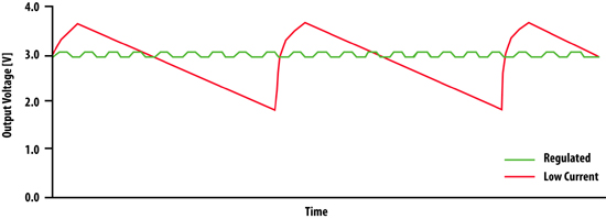
Figure 3. This figure shows a typical output voltage curve of a boost converter under different loads. At light or no load (green curve), the measured transition time (rising voltage) is hundreds of microseconds, while the idle time (falling voltage) is a few seconds. It should be noted that this change occurs when the MCU is in the power saving mode or the power consumption is extremely small. In the main operating mode, the active regulation mode, the output voltage remains stable (3V +/- 100mV) (red curve). 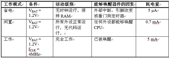
Table 1. The ultra-low power MCU has multiple sleep modes, so when only limited functions are required and the entire MCU is not required to work in a high-power operating mode, developers can configure an ultra-low power in different low-power idle modes Consume MCU. 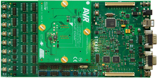
Figure 5. Using the STK600 and ATtinyx3U top-level module and other demonstration tool kits, developers can measure power efficiency under actual operating conditions. These tool kits allow developers to fully use the functions of ATtiny43U and Ateml's rich and mature development tool kits to test single-cell operation, obtain the power curve of high-brightness LEDs, and adjust the power threshold to fully utilize the maximum capacity of the battery within a safe range. 