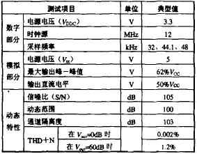
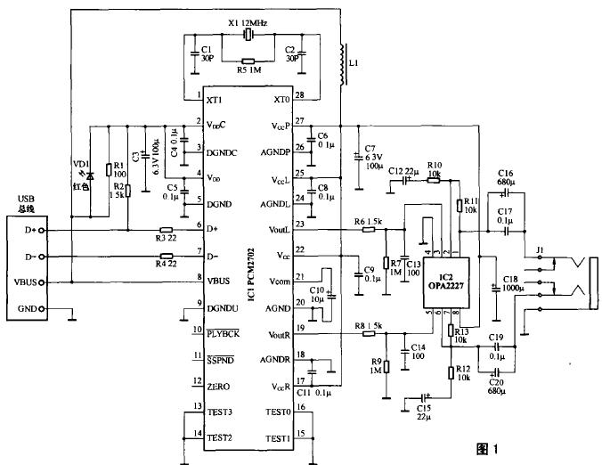
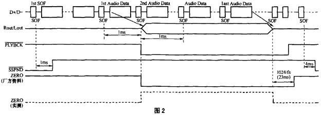
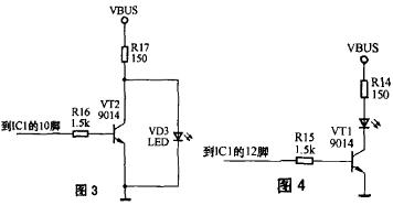
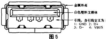
USB sound card production method This article introduces a sound card with USB interface, the effect is quite good, the circuit is also very simple. Circuit principle The circuit schematic is shown in Figure 1. PCM2702 (IC1) is a USB interface DAC chip produced by BB, a subsidiary of American TI. PCM27O2 supports USB1.0 standard and can receive 16bit stereo or mono USB audio data stream. Its basic parameters are shown in Table 1. IC2 is an integrated dual op amp used as an output buffer amplifier. The left side of IC1 is the digital input part, and the right side is the analog output part. Pin 2 of PCM2702 requires a voltage of 3.3V. Here, a red light-emitting tube is used to step down the voltage ingeniously and double as the Power Supply indicator. It will light up and connect R1 to reduce the burden of LED. R2 is a pull-up resistor. Considering that the high-frequency ripple of the power supply provided by the computer is large, strong filtering measures are adopted. C3 ~ C11 and C18 are power supply filter and decoupling capacitor, add an inductance for analog part of the filter. The audio output bias of PCM2702 is 1 ~ 2Vcc. Because the buffered op amp connected later is a single power supply application, no DC blocking capacitor is added, so the op amp does not need to add a bias resistor. IC2 constitutes a buffer amplifier with a DC amplification factor of 1 and an AC amplification factor of 2, and C16, C17, C19, and C20 are DC blocking capacitors. If the output resistance of the op amp is ignored, the calculation formula of the DC blocking capacitor capacity is as follows: C = 7 / (6πfLRL) In the formula, fL is the lower limit frequency, and RL is the load impedance. If the lower limit frequency is set to 40Hz, two headphones are used in parallel. Since the impedance of an ordinary headphone is usually 32Ω, then RL is 16Ω, and the DC blocking capacitor value can be calculated to be 580.5 uF, here use 680uF, and a 0.22uF CBB capacitor can improve high frequency sound quality. Of course, since the output of PCM2702 already has a large amplitude, you can directly promote low-power amplifiers such as TDA2282, so you can change the op amp to a power amplifier, so that the output power will be larger. Pins 11 to 13 of PCM2702 are status mark pins. The data provided by the manufacturer pointed out that the 10-pin state is high when there is no audio signal, and it becomes low when the header of the second frame of audio data arrives, and does not become high until the end of the second frame of audio data. Level. As long as there is data input, pin 11 is high. Pin 12 is at a high level from the beginning of the first frame of data to the beginning of the second frame, and then at a low level during the normal input of the audio data signal, or if the audio signal continues for 1024 sampling periods to zero, then It is high level. Figure 2 is a timing diagram of the state of these three pins. According to this, the signal output from pin 10 can be added to an inverter to drive the LED as a work instruction, as shown in FIG. 3. However, it was found in the actual measurement when playing music that during the entire input process of the audio data stream, the 12 pin has maintained a high level. Once the music stops, the 12 pin will become a low level. Therefore, the 12-pin signal can also be used to drive the work instruction circuit. At this time, the circuit is shown in Figure 4. Compared with the latter, the two application solutions have strict indication meaning, but the power consumption is slightly larger. Component selection The withstand voltage value of all electrolytic capacitors should be above 6.3V, and the resistance power should be 1 / 4W except R17, and the remaining 1 / 16W should be sufficient. C12, C15, C16, C17, C19, C20 have a great impact on the sound quality, high-quality capacitors should be used. L1 can be self-made, and it can be wound around 10 turns with a thick enameled wire on a small magnetic core (both cylindrical and ring-shaped). For the convenience of use, in this circuit, the power supply voltage is directly taken from the USB 5V positive power supply. Therefore, low-voltage op amps should be used, preferably single-supply op amps. This circuit design is designed to take into account the convenience of use. If necessary, the peripheral power supply can be used to power these two chips, and the effect will be better. Figure 5 is the pin definition of the USB cable A head socket on the computer. This USB sound card does not need to be debugged, it is ready to install. Computers with operating systems above Windows 2000 do not need to install drivers, and the system can automatically recognize them. The disadvantage is that there is only audio output and no input.
High efficient charging speed for Lenovo and IBM laptop, stable current outlet can offer power for the laptop at the same time charge the laptop battery. The best choice for your replacement adapter. We can meet your specific requirement of the products, like label design. The plug type is US/UK/AU/EU.The material of these products is PC+ABS. All condition of our products is 100% brand new.
Our products built with input/output overvoltage protection, input/output overcurrent protection, over temperature protection, over power protection and short circuit protection. You can send more details of this product, so that we can offer best service to you!
Lenovo Adapter,Charger For Lenovo,Power Supply For Lenovo,Adapter For Lenovo Mini Shenzhen Waweis Technology Co., Ltd. , https://www.waweis.com