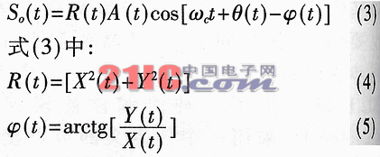
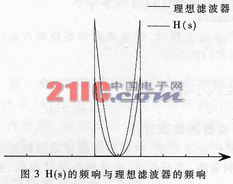
Abstract: This paper introduces a method for developing a channel simulator that simulates the basic characteristics of mobile channels in real time (such as Rayleigh fading, multipath propagation, radio wave propagation path loss, Doppler frequency shift, etc.), including the simulator digital principle and its implementation Program. The fading rate of this simulator is adjustable from 8 to 80 Hz, the simulated fading depth exceeds 20 dB, and the maximum multipath delay is 10.2 μs. 1 Development background of mobile communication channel simulator Mobile communication is a communication method that has developed very rapidly in recent years. In land mobile communication systems, due to the complex terrain of the area where the mobile station is located and the movement of the mobile station itself, the envelope and phase of the received signal change randomly. In order to evaluate the performance of mobile communication devices, it is necessary to carry out repeated experiments in the actual communication environment, which will consume a lot of manpower and material resources. In order to shorten the development cycle and save development costs, various channel simulators are widely used in the development of mobile communication devices. This article introduces a simulator for mobile communication channels with a signal frequency of 70MHz and a base station antenna height of 18m. The simulator can simulate the main characteristics of mobile communication channels, such as Rayleigh fading, multipath propagation, battery propagation path loss, and Doppler frequency shift. 2.1 Rayleigh's decline Land mobile communication is affected by factors such as terrain and environment, and its fading mechanism is very complicated. But among the many channel parameters simulated by the mobile communication channel simulator, Rayleigh fading with frequency selectivity dominates. That is, the realization of the Rayleigh distribution of the signal envelope and the uniform distribution of the phase is the core of the channel simulation. 2.1.1 The mathematical principle of Rayleigh fading Let a random process ξ (t) be expressed as: In equation (1), ξc (t) and ξs (t) are the in-phase and quadrature components of ξ (t), respectively. It can be proved that in a narrow-band stationary Gaussian process with mean zero, the in-phase component ξc (t) and the orthogonal component ξs (t) are also stationary Gaussian processes, and the mean is zero and the variance is the same. In addition, ξc (t) and ξs (t) obtained at the same time are not related or statistically independent. It can also be proved that for a stationary Gaussian narrow-band process with mean zero and variance σ2ξ, the one-dimensional distribution of its envelope follows Rayleigh distribution, and its one-dimensional distribution of phase follows uniform distribution, and as far as the one-dimensional distribution is concerned, both It is statistically independent. In summary, for a stationary Gaussian narrow-band process with mean zero, the one-dimensional distribution of its envelope follows Rayleigh distribution, and its phase follows uniform distribution, and the two are statistically independent. At the same time, a narrow-band stationary Gaussian process with mean zero can also be synthesized by two in-phase and quadrature components that are also stationary Gaussian processes. 2.1.2 Single-path Rayleigh fading Set the single-path fading channel input as: In equation (2), A (t) and θ (t) are the actual amplitude modulation and phase modulation of the carrier signal of frequency ωc, respectively. Modulated with two independent Gaussian random variables of X (t) and Y (t), the output signal So (t) can be expressed as: Therefore, the random envelope R (t) is Rayleigh distribution, and the random phase φ (t) is uniformly distributed in the range of 0 ~ 2л. It can be seen from the above derivation: quadrature modulation of the input signal is a single-path frequency-free selective Rayleigh fading simulation, which can achieve random interference of the amplitude and phase of the input signal according to the requirements, thus achieving (3) Mathematical model. 2.1.3 Multipath Rayleigh fading To simplify the analysis, let the input be a single frequency sinusoidal signal After multipath transmission, the output is: In formula (7): αi is the amplitude main weighting coefficient, τi is the time delay, φi is the random phase, and N is the number of paths. In the case of only two paths, the output amplitude is: That is, there is a delay difference between the two paths, Δτ ≠0, and the field strength of the composite signal changes with the frequency ω. In actual mobile communication channels, due to multipath transmission, the delays of the paths are different, and the relative delay difference is also different, resulting in frequency selective fading. 2.2 Multipath propagation 2.2.1 Selection of the number of multipath propagation paths In mobile communications, when there are more than two scatterers, there must be frequency selective fading in the received signal. This simulator uses three paths, that is, it can produce three channels of independent fading, so as to simulate the actual communication environment more realistically. 2.2.2 Determination of multipath propagation delay value The typical maximum measured multipath delay is 20μs [1], the domestic test result is 15μs, and the root mean square delay is about 10μs [1,2,3]. This scheme uses a variety of delays to choose flexibly in order to accept the rms delay of the actual channel. The total delay is a minimum of 0.2μs, the maximum is 10.2μs, and includes the direct path (the delay is 0). 2.3 Determination of radio wave propagation path loss At present, people generally use Okura's empirical model to predict the propagation path loss of land mobile communications. However, the application range of Okumura model is: frequency 100MHz ~ 1500MHz, base station antenna height 30m ~ 200m, mobile station antenna height 1m ~ 10m, transmission distance 1km ~ 20km. The simulator developed for the signal frequency of 70MHz, the height of the base station antenna is 18m. This is inconsistent with the application scope of the Okumura model, so the model cannot be directly applied to this scheme. Chinese American communication expert Mr. Li Jianye proposed the Lee model of radio wave propagation prediction. The model does not specifically limit the height of the base station antenna. The idea is to first obtain the signal transmission loss between regions and then to obtain the transmission loss between specific points. Because this simulator simulates the typical path loss in a general environment, there is no need to accurately simulate the point-to-point transmission specific to a certain area. Therefore, the calculation of the zone-zone radio wave loss of the Lee model is suitable for the simulation scheme, and no error correction is needed. To calculate the propagation loss with the Lee model, it is necessary to know the determined loss value at a propagation distance of 1 mile (or 1 km) in each environment in advance. The simulator simulates the general environment and does not need to be measured in the field. Therefore, the Okumura model is used to calculate the typical value of the broadcast room at a distance of 1km under the general environment, and then converted to the Lee model. In other words, the developed simulator uses the Okumura model and the Lee model to calculate the propagation loss. The specific propagation loss is shown in Table 1. 2.4 Doppler frequency shift In mobile communications, Doppler frequency shift is a widespread phenomenon, fd = v / λ (9) In equation (9), v is the speed of the mobile station, and λ is the wavelength of the signal. For an actual channel with a channel path uniformly distributed in azimuth, the shape of the radio frequency spectrum is: In equation (10), ωd is the angular frequency corresponding to the maximum Doppler shift generated by the mobile station motion, namely: In order to generate this spectrum, the Gaussian noise used for modulation must have a low-pass spectrum, as shown in equation (12): 3 Implementation method of channel simulator It can be seen from the previous discussion that the main functions of this mobile communication channel simulator are Rayleigh fading, multipath propagation, radio wave propagation path loss, Doppler frequency shift, etc. 3.1 Realization of Rayleigh fading According to equation (1), the realization method of Rayleigh fading is to use the input signal with two uncorrelated low-frequency Gaussian noise quadrature modulation to simulate Rayleigh fading with an envelope that is Rayleigh distributed and a phase that is uniformly distributed. The spectrum is determined by the spectrum of low-frequency Gaussian noise. Multipath Rayleigh fading can be synthesized from single-path Rayleigh fading after a delay. 3.1.1 Generation of low-frequency Gaussian noise The bandpass Gaussian process spectrum determined by equation (10) is shown in Figure 1. The corresponding low-pass Gaussian process spectrum is shown in Figure 2. H (s) = 1 / [(0.897s 2 + 0.31s + 1) (0.897s 2 + 0.31s + 1) (0.31s + 1)] Figure 3 shows the difference between the frequency response of H (s) and the ideal filter. The above analog filters are exchanged to obtain corresponding FIR filter tap coefficients. Use MATLAB software to generate Gaussian white noise, input this white noise to the FIR filter above, and the filter output is the required narrow-band Gaussian process. The output of the narrow-band Gaussian process is set to DA, after filtering, amplification and impedance matching, the input is processed in the next stage. 3.1.2 Realization of quadrature modulation There are many ways to achieve quadrature modulation. The mobile channel simulator uses the I / Q modulator of Mini Company to implement quadrature modulation. Its structure is shown in Figure 4. 3.2 Implementation of multipath propagation In order to realize the simulation of multipath propagation, the Mini company's power divider (referred to as power divider) is used to split the input signal. First of all, two-way power distribution is performed on the input signal: one way simulates the direct channel; the other way performs three-way power distribution. After this different delay and narrow-band Gaussian quadrature modulation, power synthesis is performed, and the output signal simulates multipath propagation. In this channel simulator, the selection of the propagation path and the delay are made by controlling the analog switch. 3.3 Realization of simulated path loss In order to simulate the path loss of propagation, this channel simulator uses a combination of fixed attenuator and numerical control attenuator for control. The basis for achieving attenuation control is Table 1. 3.5 Implementation method of Doppler frequency shift It can be seen from the conclusion of 3.1 that the Doppler frequency shift can be achieved by controlling the spectrum of the narrow-band Gaussian process. In this simulator, the spectrum control of the narrow-band Gaussian process can be achieved by changing the DA conversion rate of the narrow-band Gaussian process, thereby realizing the simulation of Doppler frequency shift. 3.6 Implementation of system control and human-machine interface The system control adopts the embedded operating system based on single-chip AT89C52, which can realize the control of data-controlled attenuator, analog switch, etc., and achieve a good human-machine interface through the keyboard and LCD. 4 Conclusion 4.1 General introduction The overall structure of this channel simulator is shown in Figure 5. 4.2 Functional indicators 4.3 Description of main index test methods 4.3.1 Rayleigh fading test method Observe the simulator output waveform with TEKTRONIX oscilloscope TDS3052, as shown in Figure 6, it can be seen that its envelope is Rayleigh distribution. Use the LC584A oscilloscope of Lecroy Company to test the Lissajous figure. Figure 7 shows the accumulated oscilloscope image of the storage oscilloscope for 10s. The figure uses two mutually orthogonal low-frequency Gaussian noise to control the horizontal and vertical deflection of the oscilloscope respectively. Because the deflection control of the noise has a relative orientation of 90 °, the resulting display image is equivalent to the polar coordinates of the random variable vector of the Rayleigh fading signal output by this simulator. In Fig. 7 on the arc of any fixed radius with respect to the origin, the uniformity of the spot intensity indicates that the phases are evenly distributed. This article introduces the design and implementation of a mobile communication channel simulator. In this simulator, the signal is modulated in the I / Q modulator with upper and lower frequency Gaussian noise to simulate the Rayleigh distribution in the actual channel. Low-frequency Gaussian noise data is generated using digital methods and Matlab software and stored in EPROM. The noise frequency can be adjusted by changing the access rate when the simulator is working, and the Okura model and Lee model are used in combination to calculate the radio wave path propagation loss. After actual testing, all the indicators of this simulator can meet or exceed the requirements of the technical indicators. At present, this simulator has been put into practical application. ECG Trunk Cable,ECG Wire,ECG Patient Cable,ECG Lead Wire Dong guan Sum Wai Electronic Co,. Ltd. , http://www.sw-cables.com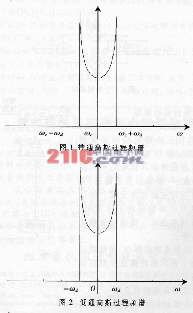
2 Development basis of mobile communication channel simulator ![]()
![]()
![]()


Table 1 Path loss of radio wave propagation Propagation distance 1km 8km 15km 25km Propagation loss Straight path 69dB 87dB 91dB 93dB city ​​environment 98dB 134dB 145dB 154dB Quasi-suburban environment 91dB 127dB 138dB 147dB Open environment 75dB 111dB 122dB 131dB 
![]()

Considering that the frequency response of the filter represented by Eq. (12) is not a rational fraction, it cannot be constructed directly, and only a digital approximation method can be used. From reference [2], the frequency response of the required filter is: 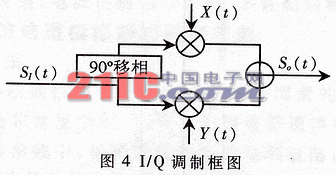
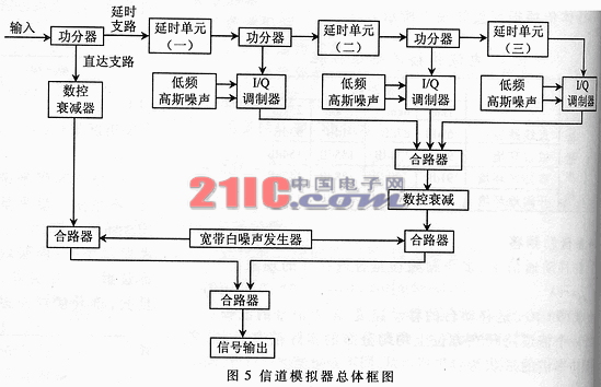
After the signal is input, it is divided into two channels: one channel is used as a direct branch; the other channel is divided into two channels after delay, one of which is modulated by an I / Q modulator on the two channels of independent low-frequency Gaussian noise. The signal envelope is Rayleigh distribution, and the phase is uniformly distributed, thereby achieving single-path Rayleigh fading without frequency selectivity; the other way is sent to the next delay unit, which is important for the above process. The output of various I / Q modulators is added at the combiner, and the amplitude envelope of the output signal is Rayleigh distribution, and the phase is uniformly distributed. With the initial direct signal, it can also simulate the Rice channel. The actual path loss is simulated by controlling the numerical control attenuator. In the direct and delay paths, adjustable white noise is superimposed separately to achieve adjustable output signal-to-noise ratio. 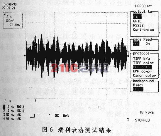
4.3.2 Fading waveform phase distribution test method 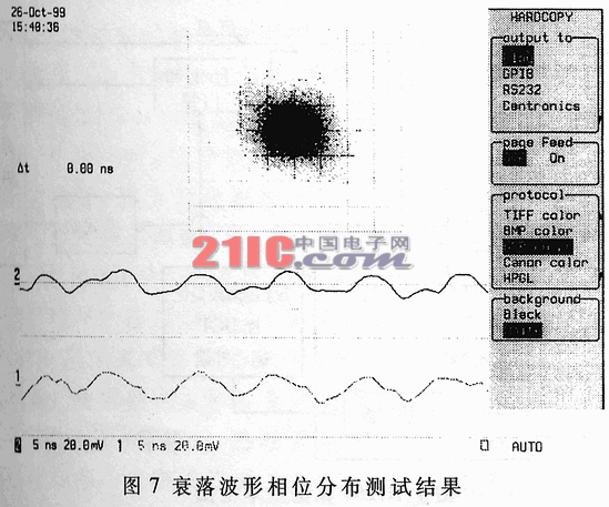
4.3.3 Other index test methods