ã€Abstract】 Using the all-round OrCAD hybrid circuit simulation Pspice A / DV9 software, the phase discriminator in the OKI (900) mobile phone signal transmission circuit was simulated.
We are manufacturer of Cable Accessories in China
Optical Cable Accessories Factory
China Optical Cable Accessories,Cable Accessories,Optical Cable Accessories,Fiber Optic Storage Frame,Opearation Is Convenient, Optical Cable Accessories Factory Shandong Qingguo Optical Fiber Co., Ltd. , https://www.qgfiber.com
Keywords: Electronic Noise Simulation Analysis Phase Detector This article uses the all-round OrCAD hybrid circuit simulation Pspice A / DV9 software launched by OrCAD in March 2000 to noise the phase detector in the OKI (900) mobile phone signal transmission circuit Simulation, by analyzing the simulation results, we have a fuller understanding of the characteristics of circuit noise. It should be mentioned that Pspice A / DV9 is powerful. It can not only perform noise simulation on the circuit, but also perform DC sweep analysis on the circuit. AC scanning analysis, transient analysis and temperature analysis, etc., if the circuit designer masters this weapon, it will help to improve the efficiency of circuit design.
1 The generation of noise In electronic circuits, noise mainly comes from two aspects:
(1) Resistance thermal noise is generated by the thermal motion of internal free electrons. Free electrons often collide with each other in thermal motion, and the speed and direction of their motion are irregular. The higher the temperature, the more intense the motion. This thermal movement of free electrons creates a very weak current in the semiconductor. This disordered and undulating state is called the undulating noise current. Fluctuating noise current flowing through the resistor will produce fluctuating noise voltage across it.
Because the fluctuation of the fluctuation noise voltage is irregular, its instantaneous amplitude and instantaneous phase are random, so its instantaneous value cannot be calculated. The average value of the fluctuation noise voltage is zero, and the noise voltage is irregularly deviated from this average value However, the mean square value of the fluctuating noise voltage is determined and can be measured with a power meter. Experiments have found that in the entire radio frequency band, when the temperature is constant, the average power consumed by the unit resistance is almost a constant in the unit frequency band. In contrast to the phenomenon that white light contains all visible light wavelengths, people regard this in the entire radio frequency band The undulating noise with a uniform frequency spectrum is called white noise.
(2) Transistor noise Transistor noise mainly includes thermal noise, heat radiation noise, distribution noise and flicker noise. Among them, the thermal noise and heat radiation noise are white noise, and the rest are colored noise.
Thermal noise: Irregular thermal movement of electrons in a transistor generates thermal noise. It mainly exists in the base resistance, and the thermal noise of the emitter and collector is generally small and can be ignored.
Heat dissipation noise: because minority carriers are injected into the base through the PN junction, the number of them is random even under current operation, that is, the number of carriers input into the base in a unit time is different, so the carriers reaching the collector The number is also different, and the noise caused by this is called heat radiation noise. The heat dissipation noise is specifically manifested as the fluctuation of the emitter current and the collector current.
Distribute noise: In a transistor, most of the unbalanced carriers passing through the emitter junction reach the collector junction, forming a collector current. The distribution ratio of the two parts of the current is random, which causes the collector current to fluctuate up and down at the static value, which generates noise. This is the distribution noise.
Distribution noise is actually a kind of heat dissipation noise, but its power spectral density changes with frequency. The higher the frequency, the greater the noise.
Flicker noise: The mechanism for generating this noise is not yet clear. It is generally believed to be caused by poor cleaning or defects on the surface of the transistor. Its characteristic is that the spectrum is concentrated in the low frequency range below about 1kHz, and the power spectral density decreases with frequency While increasing, flicker noise can be ignored when working at high frequencies.
2 Principle analysis of phase discriminator Phase discriminator is a phase comparison device used to detect the phase ui (t) of the input signal and the phase uo (t) of the feedback signal, and its output is an error that is a function of uo (t) signal ![]()
The characteristics of this error signal can be various, including sinusoidal characteristics, triangular characteristics, sawtooth characteristics and so on. This article uses a sinusoidal characteristic, which is formed by an analog multiplier and a low-pass filter (LPF) connected in series, as shown in Figure 1. 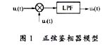
Suppose the multiplication coefficient of the multiplier is Km [unit is 1 / V], the input signal ui (t) and the feedback signal uo (t) are multiplied by: 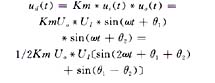
After passing through a low-pass filter (LPF) to filter out the 2ω component, the error voltage is obtained: ![]()
The phase detection characteristics of the phase detector are:
ud (t) = Ud * sinθe 
3 Noise Simulation of Phase Detector This article uses Pspice A / DV9 software to simulate the noise of the phase detector. The specific steps are as follows.
(1) Draw the circuit diagram and set the AC parameters.
· Create a project file, use the Pspice \ NewSimulaTIonProfile option, and enter the name of the simulated circuit file in the SimulaTIon dialog box.
· Select the ACSweep item in the SimulaTIon SetTIng drop-down menu to perform communication analysis.
· Set the parameters of noise analysis in the Noise Analysis column. The settings are as follows:
Enable: Noise analysis function, tick with the mouse.
Output Voltage: Specifies to perform noise analysis on this output voltage node or the voltage difference between the two nodes, which is now set to Vo (Vo).
I / VSource: Specify the equivalent input noise source. In fact, the noise of each file is merged into the signal source in the form of root mean square. This article takes VS · RC.
Internal: Set the frequency of the text output file interval. If not set or set to 0, no output record will be generated.
(2) Archive and execute Pspice.
· Archive with File \ Save.
· Click the Pspice \ Run function to start Pspice to execute the simulation, and the Probe window will automatically open on the screen.
(3) Use Probe to observe the results.
· Using the Trace \ Add Trace option of the Probe empty image, open the Add \ Trace dialog box, select V (ONOISE), and adjust the horizontal axis coordinate range to observe the spectrum distribution of the equivalent output noise (see Figure 3). 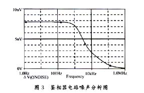
· It can be clearly seen from the output noise spectrum in Figure (3): At high frequency, the curve is curved downward, that is, the noise amplitude becomes smaller. If at low frequency, the noise curve is slightly higher, which shows that the circuit is at low frequency It is more susceptible to noise interference. For the values ​​of noise interference of the components in the circuit, please refer to the content of the output text file generated by Probe.
This article only analyzes the noise of the phase detector circuit. Using the same method, it can also perform DC sweep analysis, transient analysis and temperature analysis on the circuit. In view of the space relationship, I will not describe them one by one here.
2 Edited by Zheng Guangqin. Almighty OrCAD mixed circuit simulation Pspice A / D V9. China Railway University Press, 2000
3 Edited by Yu Ming and Wu Jiang. Big Brother's maintenance and repair. Beijing: People's Posts and Telecommunications Press, 1999
ADSS OPGW Cable Accessories
Aerial Cable Accessories
Technology: Forging&Machining
Material: Stainless Steel, Hot dip galvanized steel
Surface: Hot dip galvanized flat iron
Preformed Suspension Clamp:
Structure and Raw Material:
Metal Joint Box for ADSS,OPGW Cable:
Cable Storage Shelf
Fix Clamp(GXJ)
Stainless Steel Band
Down Lead Clamp:

references
1 Du Wulin editor. Principle analysis of high frequency circuit. Xi'an: Xi'an Electronic Technology Press, 1999