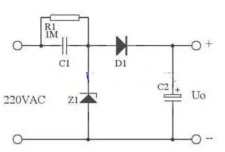
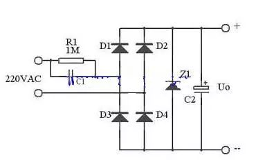
First, let's explore the principle of capacitor step-down. The basic idea is to use the capacitive reactance of a capacitor to limit the current in an AC circuit. At a standard frequency of 50 Hz, a 1 μF capacitor creates a capacitive reactance of approximately 3180 ohms. When connected to a 220V AC supply, this results in a maximum current of about 70 mA through the capacitor. However, it’s important to note that the capacitor itself doesn’t consume power; instead, it stores and releases energy, which means the current is reactive rather than real. This characteristic makes the capacitor useful for current limiting. For example, if you connect a resistive load like a 110V/8W bulb in series with the capacitor, the bulb will light up normally without being damaged. The current required by the bulb (around 72 mA) matches the current-limiting capability of the 1 μF capacitor. Similarly, a 5W/65V bulb can also be used with the same setup, as its operating current is close to 70 mA. In essence, capacitor step-down works by using the capacitive reactance to control the current flow. The capacitor acts as a dynamic voltage divider, sharing the voltage between itself and the load. This method is often used in low-power applications where isolation is not critical. The following diagram shows a typical application of a capacitor step-down circuit. C1 is the step-down capacitor, R1 is a bleeder resistor to discharge the capacitor when the power is off, D1 is a half-wave rectifier, and D2 provides a discharge path during the negative half-cycle. Z1 is a Zener diode used for voltage regulation, and C2 is a filter capacitor to smooth the output. In some practical designs, the Zener diode is used both for voltage regulation and for providing a discharge path. This configuration allows the capacitor to safely discharge during the negative half-cycle of the AC signal, ensuring the circuit remains safe and functional. For higher current applications, full-wave rectification is often preferred. This approach improves efficiency and reduces ripple in the output. A full-wave rectified circuit is shown below: At small voltages, the maximum output current from a full-wave rectified circuit depends on the capacitance of the step-down capacitor. The formula for calculating the capacitive reactance is Xc = 1/(2πfC), and the current through the capacitor is Ic = U/Xc = 2πfCU. When using capacitor step-down, there are several important considerations: 1. Choose the capacitor based on the load current and AC frequency, not the voltage or power of the load. 2. Use non-polar capacitors with a voltage rating above 400V. Electrolytic capacitors should never be used. 3. Capacitor step-down is not suitable for high-power or dynamic loads due to safety concerns. 4. It is also unsuitable for capacitive or inductive loads. 5. If DC operation is needed, prefer half-wave rectification over bridge rectification, especially under constant load conditions. Next, let's look at the device selection process. When designing the circuit, first determine the exact load current. Then, choose the step-down capacitor based on the expected current. The larger the capacitance, the lower the reactance, allowing more current to flow. However, if the load current is less than the capacitor's maximum current, the excess will go through the Zener diode, potentially causing it to fail if not properly rated. To ensure safe operation, the capacitor's voltage rating must be greater than twice the supply voltage. Additionally, the bleeder resistor must be chosen to allow the capacitor to discharge within a specified time frame. As a design example, consider a 0.33 μF capacitor connected to a 220V/50Hz AC source. The capacitive reactance is calculated as Xc = 1/(2πfC) = 9.65 kΩ. The resulting current is Ic = 220 / 9.65 ≈ 22 mA. In general, the relationship between the capacitor value and the load current can be approximated as C = 14.5 × Io, where C is in microfarads and Io is in amperes. Capacitor step-down is a simple but effective technique for low-power applications. However, it is a non-isolated power supply, so special attention must be given to electrical safety to prevent shocks or damage. The DAB (Digital Audio Broadcasting) Splitter is a crucial element in modern audio distribution systems, designed specifically to divide a single input signal evenly across multiple output channels while ensuring that each channel remains isolated from the others. This functionality is paramount in ensuring high-quality audio transmission across various devices, enabling broadcasters and entertainment venues to deliver crisp, clear sound to every corner of their establishments, particularly in settings where seamless signal distribution is absolutely essential. DAB Spliter,DAB Spliter SMA,DAB Spliter for Car,DAB Spliter Signal Amplifier,AM /FM DAB Antenna Yetnorson Antenna Co., Ltd. , https://www.yetnorson.com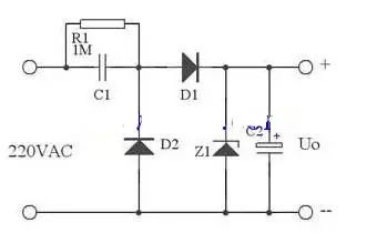
The core function of a DAB Splitter lies in its ability to distribute an incoming signal into two or more identical outputs, typically ranging from 2-way distribution (where the signal is split into two equal parts) to higher numbers like 3-way or even more, depending on the model and application requirements. This process ensures that every device connected to the splitter receives an equal and undistorted portion of the original signal, eliminating the need for separate signal sources for each receiver.
Unlike traditional cable TV distributors, which merely transfer a portion of the signal's energy to the next stage, DAB Splitters are designed with isolation in mind. This isolation feature is crucial in preventing signal interference and ensuring that each output channel operates independently, maintaining signal integrity and clarity. In broadcast environments, where multiple speakers or audio devices may be connected to a single source, this isolation is especially important to prevent crosstalk or feedback that can compromise audio quality.
In cable television networks, branch devices are commonly used to distribute signals, but they differ significantly from DAB Splitters in their function and purpose. While branch devices may be suitable for transferring energy to subsequent stages in a cable network, they lack the isolation and equal distribution capabilities that are vital for high-fidelity audio transmission.
The versatility of DAB Splitters makes them indispensable in a wide range of applications, including but not limited to radio stations, concert venues, public address systems, and even home entertainment setups. They enable users to effortlessly expand their audio systems, adding new speakers or devices without compromising the quality of the original signal.
In summary, the DAB Splitter is a vital component for efficient and high-quality signal distribution in audio and broadcast systems. By dividing an input signal equally among multiple isolated outputs, it ensures that every device receives a clean, undistorted audio signal, making it an essential tool for professionals and enthusiasts alike.