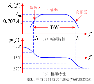
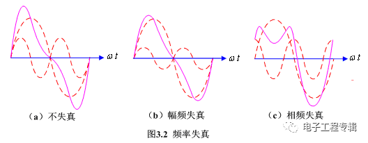
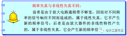
Understanding the frequency response of an amplifier is essential for analyzing its performance across different frequencies. This section explores the frequency characteristics of a common-emitter circuit, provides a qualitative analysis of its behavior, and introduces key concepts such as f_L (lower limit frequency), f_H (upper limit frequency), and BW (bandwidth). It also discusses frequency distortion and how it affects signal integrity. 3.1.1 Representation of Frequency Response The frequency response of an amplifier can be represented as: Ȧu(f) = Au(f) ∠φ(f) Where: Figure 3.1 illustrates the amplitude and phase frequency characteristics of a typical single-transistor common-emitter amplifier. From the amplitude curve, we observe that the gain decreases in both the low-frequency and high-frequency regions. This is due to the influence of coupling capacitors at lower frequencies and inter-electrode capacitances at higher frequencies. Causes of Gain Reduction: In the low-frequency range, as the frequency decreases, the capacitive reactance of the coupling capacitor increases, leading to a greater voltage division effect. This results in less voltage being applied to the input of the amplifier, causing the output voltage to drop and the overall gain to decrease. In the high-frequency range, the capacitive reactance of the transistor's internal capacitances decreases, increasing their shunting effect. This reduces the actual current being amplified, thereby lowering the gain. From the phase-frequency characteristics, we can see that in the low-frequency band, an additional phase shift of Δφ from 0° to 90° occurs compared to the mid-frequency range. In the high-frequency band, an additional phase lag of Δφ from 0° to -90° is observed. 3.1.2 Lower Limit Frequency, Upper Limit Frequency, and Bandwidth fL is the lower limit frequency, marking the point where the gain begins to drop significantly at lower frequencies. fH is the upper limit frequency, where the gain starts to decline at higher frequencies. BW stands for bandwidth, calculated as BW = fH - fL. The bandwidth indicates how well the amplifier can respond to signals of various frequencies. A wider bandwidth means better frequency response and is a crucial parameter for evaluating the performance of an amplifier. 3.1.3 Frequency Distortion Frequency distortion occurs when the amplification circuit cannot maintain a flat gain and consistent phase shift across the entire frequency range. This leads to differences in amplification and phase shifts for different frequency components of the input signal, resulting in waveform distortion. There are two types of frequency distortion: For example, consider an input signal containing two sinusoidal components at frequencies f1 and f2. If the amplifier treats both frequencies equally in terms of gain and phase shift, the output remains undistorted, as shown in Figure 3.2(a). However, if the gain for f2 is reduced, the output becomes distorted, as seen in Figure 3.2(b)—this is amplitude-frequency distortion. Similarly, if the phase shift differs between f1 and f2, the output waveform will also distort, as shown in Figure 3.2(c)—this is phase-frequency distortion. 3.6kw solar power inverter,gootu hybrid inverter single phase,dc to ac solar inverter 3.6kw,3.6kw hybrid solar inverter,3.6kw 24v hybrid inverter,3kw solar inverter,off grid solar inverter,soler inverter solar home system,hybrid solar system,off grid sola Shenzhen Jiesaiyuan Electricity Co., Ltd. , https://www.gootuenergy.com