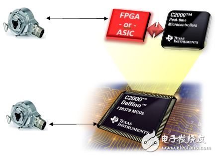
Many industrial inverters and servo drive manufacturers rely on field-programmable gate array (FPGA) or ASIC technology to implement commercial off-the-shelf (COTS) products for a long time, such as 32-bit microcontrollers (MCUs). The function. However, adding FPGAs or ASICs to software programmable controllers to support position sensor feedback or incremental-accumulation filtering increases system cost and development complexity. In this blog series, we will take a look at the history of industrial drive and servo control architectures, the challenges of introducing FPGAs into these architectures, and how the new capabilities of Industrial Drive Control SoCs (COTS MCUs) change. The cost-effective model enables today's industrial drives to no longer use FPGAs. So how does FPGA become the usual practice in inverter drive and servo control architectures? For example, when off-the-shelf products were unable to implement new system functions at the time, many developers had to implement their specific PWM/IGBT protection mechanisms outside of the MCU. Others may feel that their current loop timing is too short to be processed by a programmable MCU, but only through the cooperation of logic gates and software. Once an FPGA is used in the system, this device will become an aid to system design. Although it is a logic aid, it will be able to introduce new technologies introduced by the evolving driver and servo market. Support for these technologies is integrated. For example, the functionality of the FPGA has been extended to integrate clockwise/counterclockwise (CW/CCW) and pulse train (PTO) ports that communicate with PLCs and motion controllers. In addition, FPGAs have become the target devices in the system to support emerging standards and proprietary position sensor interfaces such as EnDat and BiSS. Furthermore, the interface to the isolated incremental-accumulated ADC modulated output (usually based on a sinusoidal filter) is also integrated inside the FPGA device. In addition, several Industrial Ethernet standards also provide MAC controllers on the FPGA gate. All of these different features quickly accumulate the number of gates to hundreds of thousands, making FPGAs very expensive. Figure 1: Comparison of SoC and MCU with FPGA architecture Although the expansion of this driver function has been absorbed by the FPGA, an interesting new market dynamic is emerging. The directory controller begins to provide these functions on-chip, making ready-to-use features available to the driver developer. The difference is substantial: on-chip functionality is immediately available to developers—that is, to buy MCUs in the catalog without having to construct these solutions with FPGAs. This is directly related to reducing system cost and saving board space, which is not possible with FPGA solutions. With the advent of the new Drive Control SoC, such as the C2000TM F28379 MCU that supports the DesignDRIVE Location Manager technology, developers can now avoid many of the shortcomings mentioned above. In the next part of this series, we further explore other challenges encountered when introducing FPGAs into drive and servo control architectures. Pet Cage Box, Pet Carrier box, Pet cage, pet carrier house Pet Cage Box, Pet Carrier box, Pet cage, pet carrier house Ningbo Multitasking Electronic Co.,Ltd , https://www.smartmultesic.com