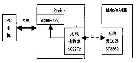
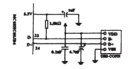
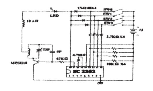
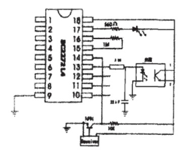
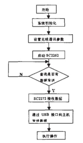
Abstract: Universal Serial Bus USB is a new specification for microcomputer bus interfaces. This paper introduces a design scheme of a wireless communication keyboard controller based on USB interface, including hardware design, device driver design and application software design. This article refers to the address: http:// introduction In today's multimedia presentation environment, there is a lack of equipment that can remotely control a computer. The lecturer can only stand on the podium to operate the computer, which limits the face-to-face communication between the speaker and the audience. In order to solve this problem effectively, this paper designs a wireless communication keyboard controller device that can remotely control the computer. By integrating the USB interface with the wireless transmitting and receiving modules, an intelligent and simple wireless communication keyboard is designed. Controller. The system mainly includes a USB module, a wireless transmitting module, and a wireless receiving module. 1 overall plan The design scheme is based on the wireless transmitter/receiver. The user touches the wireless transmitting module through the button on the designed "keyboard controller", the SC2262 sends the command data, and the wireless receiver SC2272 located on the host side connection card receives the data. Rear. The data is transmitted to the microcontroller MC68HC05JB4, processed by the MC68HC05JB4 chip, and the data is finally transmitted to the host through the USB bus, and the driver sends the corresponding application software. Thereby manipulating the document to be operated. The system structure block diagram is shown in Figure 1. Figure 1 System block diagram 2 hardware design (1) connection card design In this solution, the connection port directly connected to the host through the USB port is a self-designed connection card. The card integrates two main chips to form two functional modules. The core is MOTOROLA's microcontroller MC68HC05JB4, which communicates with the radio receiver SC2272 and the host respectively. (2) MC68HC05SJB4 chip The MC68HC05JB4 chip is an 8-bit microcontroller from the MC68HC series from MOTOROLA. Through the USB module included in the microcontroller. Data communication on the USB bus can be easily realized. The MC68HCO5JB4 provides two ports connected to the D+ and D- of the cable respectively. It also provides a 3.3V reference voltage, which is connected to D1. A typical connection is shown in Figure 2. D+ and D are the signal lines of a pair of differential modes. Among them, the resistance of 1.5K is higher, and the resistance range must be 1.5KΩ±5%. USB transmits signals and power through a four-wire cable: In order to match the impedance of the cable, an unbalanced terminal is used at each end of the cable. Matching resistance. This resistor ensures that the connection or separation of peripherals to ports can be detected. And can distinguish between high speed and low speed equipment. The SCI interface circuit uses the MAX232 chip, which converts the +5V voltage used by the microcontroller to +12V and connects to the radio receiver SC2272. The received data is passed to the microcontroller. At the same time in order to generate a 1.5M USB bus speed. The system uses a 6MHz crystal. Figure 2 USB interface circuit (3) Wireless transceiver and coding, decoder design In terms of signal encoding/decoding, this design scheme uses the SC2262/SC2272 chip as the encoding/decoding chip. The connection principle is shown in Figure 3 and Figure 4. The first to eighth pins of the SC2262 and SC2272 chips have three states. That is, the power supply is positive, grounded, and floating. With these three states, there are 38 kinds of address coding modes. Radio remote control is achieved by using the same encoding for these 8 pins without interference. Figure 3 radio transmitter SC2262. Figure 4 radio receiver SC2272 In the transmitting circuit. When any of the switches in SWO-SW3 are pressed to close. The 17th pin of the SC2262 sends a coded pulse signal corresponding to the address code. The signal is sent out through the radio transmission circuit. After receiving the signal, the radio receiver connected to the SC2272 sends it to the 14th reference of the SC2272. foot. If the address code of the signal matches the address code of the SC2272 chip that received the signal. Then, the 10th to 13th data lines of the SC2272 output control signals corresponding to SW0 to SW3. More key switches can be combined by cross coding the Sw0-Sw3. According to different needs, the switch design has greater expandability. 3 software design The software design mainly includes the MC68HC05JB4 main control program, HID device driver and application software design. (1) The main control module of MC68HC05JB4. The MC68HC05JB4's main control module is designed to perform two functions and functions: First, monitor the status of the wireless receiver SC2272. Automatically generate status information and user command information; second, complete USB bus communication between the host and the connection card, and automatically handle host control and query commands. For the implementation of function two, the USB module in the MC68HCO5JB4 provides three endpoints. Endpoint 0 communicates with the host through control transfers, and Endpoint 1 and Endpoint 2 use interrupt transmission. Think of endpoint 0 as the device's control and status registers, while endpoint 1 and endpoint 2 are the device's two data buffers. Corresponds to 3 endpoints. The 68HCO5JB4 provides three control registers. Two interrupt registers (one for endpoint 1 and endpoint 2) and eight data transmit/receive registers for endpoint 0. Eight common data transmit registers are provided for Endpoint 1 and Endpoint 2. Its function is roughly divided into four modules: USB interrupt service routine: Command processor; get command module; report processor. The USB interrupt service routine processes USB different communication information, sends control information such as SETUP, IN, and 0uT of endpoint 0 to the command processor and assists the report processor to send pending reports to the interrupt breakpoint. 1. When the USB device is first Connected to the bus, it is designated as a specific address, and then the host sends a command request to detect device characteristics and select different device parameters. The command processor module analyzes these command requirements and responds with the required descriptors and parameters. The USB keyboard controller is positioned as a Human Interface Device (HID). It not only responds to standard USB protocol requirements, but also responds to HID sub-protocol requirements. At the same time, in order to complete the transmission of information. The device must also support at least one interrupt endpoint. In addition, in order for the data to be properly interpreted by the BIOS, the USB keyboard controller must be entered in the format defined by the report. The reporting processor is responsible for converting the data received by the wireless receiving module in a prescribed format and requesting the interrupt service routine to send a report through the interrupt pipe. The wireless receiving module is ready to receive data sent by the wireless transmitting module and modify the report data byte. The report processor is notified when a complete packet is received. The command processor mainly handles USB general commands and HID-specific commands. The acquisition command module is mainly to simulate the receiving function of the SCI. Since the MC68HCO5JB4 does not have an SCI module. In order to correctly receive data, the input capture (ICAP) and output compare (OCMP) functions of the 16-bit clock included in the MC68HCO5JB4 are used to simulate the SCI receive function. Each time the SCI data is received, it is stored in the buffer. Wait for a complete packet to be received. Just set the flag. The notification report processor data is ready. If USB communication is stalled. The buffer may be full and the SCI's data reception will be disabled. The reporting processor is responsible for generating standard USB reports. The unique suspend and wake-up functions of the USB keyboard controller are also an important part of the design. USB protocol provisions. When the bus is in idle state for more than 3ms. The controller must go into a suspended state. The suspended controller must draw less than 500uA from the bus. The suspend of the MC68HCO5JB4 is implemented by setting the suspend flag bit in the interrupt register of USB endpoint 0. The 500uA specified by the protocol includes the current of the cable termination matching resistor on the host side (usually 220uA), so for controllers that use bus power. Entering the suspend state usually means that the total current consumption cannot exceed 280 mA. This is actually asking the MC68HCO5JB4 to enter STOP mode. However, the MC68HCO5JB4 is disabled in STOP mode, which means that data cannot be received at this time. To solve this problem. That is, the controller does not enter the suspended state. Then, the host periodically sends an end of packet (EOP) signal to the controller, and the interval time is less than 3 ms, so that the controller is always in a normal state. (2) Application software design This design is mainly for document operation and realizes the related functions of the keyboard. The system has four control hotkeys such as "previous page", "next page", "back" and "close". The API function can be called to register the system hotkey code. The user uses the keyboard controller before. First set the document parameters that need to be operated on the host's application interface. After the control hotkey is activated, the SC2262 is touched and starts transmitting data. At this time, the host actively queries whether there is data transmission. Real-time monitoring. When the SC2272 receives the data, it sends data to the microcontroller MC68HCO5JB4 through the SCI interface circuit. Finally, the MC68HCO5JB4 sends data to the host through the USB connection 12I. After the host receives it, it performs the corresponding operation. The main flow chart is shown in Figure 5. Figure 5 software flow chart Conclusion The design scheme is suitable for classroom teaching, lectures, etc. in a multimedia-assisted environment, and can be used for remote remote computer work of up to ten meters or more, with good results. At the same time, it also provides a convenient, fast and reliable 12I solution for portable wireless communication peripheral systems. Cold Forging is a forming process below the recrystallizing temperature of the material, and it is forged below the recovery temperature. It is customary to call the forging of unheated blank cold forging in production. Most of the cold forging materials are aluminum and some alloys, copper and some alloys, low carbon steel, medium carbon steel and low alloy structural steel with low deformation resistance and good plasticity at room temperature. Cold forgings have good surface quality and high dimensional accuracy, and can replace some cutting. Cold forging can strengthen the metal and improve the strength of the parts. Round Heat Sink,Cold Forging Process,Aluminum Fin Heatsink,Aluminum Round Heat Sink Dongguan Formal Precision Metal Parts Co,. Ltd , https://www.formalmetal.com