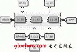
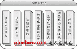
With the continuous shrinking of the automatic fingerprint recognition system and the continuous improvement of the function and speed of the microprocessor, the complex fingerprint recognition door lock control algorithm can be solidified onto a very small embedded microprocessor module. The system consisting of a fingerprint sensor and a door lock control mechanism is called an embedded fingerprint recognition door lock system. Embedded fingerprint locks are widely used in applications such as safes, laboratories, and corridors. This paper designs and implements the embedded fingerprint lock based on the fingerprint identification module, and gives a relatively complete set of software and hardware design. Fingerprint identification door lock system hardware structure The hardware structure of the fingerprint recognition door lock system mainly includes: a fingerprint identification module, a microcontroller, a read/write module, a power management and an electronic lock mechanism, and an infrared sensing circuit and a liquid crystal LCD display required for the door lock function, wherein the core part is Fingerprint identification module and microcontroller. The block diagram of the fingerprint identification door lock system is shown in Figure 1. The dotted line is the fingerprint recognition function module. Figure 1 Block diagram of the fingerprint identification door lock system Single chip microcomputer door lock control circuit The core structure of the door lock control is the microcontroller P89LPC932A1, which is a single-chip MCU, suitable for many applications requiring high integration and low cost, and can meet various performance requirements. The P89LPC932A1 integrates many system-level features to greatly reduce component count, board space, and system cost. The MCU communicates with the fingerprint identification module through the serial port to complete the fingerprint entry, deletion, and identity confirmation. After the verification, the motor control door lock performs the action of opening and closing the door. The schematic diagram of the door lock control circuit with the single chip P89LPC932A1 as the core is shown in Fig. 2. The P89LPC932A1 has up to 26 powerful I/O ports, which can meet the needs of the peripheral part of the keyboard, LCD display, indicators, buttons, buzzer and so on. The keyboard is used to enter the password. The LCD displays the user registration information and ID number. The two-color indicator and buzzer are used to remind the user whether the operation is successful or to issue an alarm. In addition, there are some remotely controlled pushbutton switches for powering up the device or performing operations related to the opening and closing of the door. The specific design can increase or decrease the peripheral components according to different application occasions and actual functional requirements, and reduce the system power consumption while satisfying the functions as much as possible. The motor control part is driven by a single-chip microcomputer to drive the motor to perform the switch lock action. In the figure, U1 is the power control chip R1121N, which outputs 3.3V to the microcontroller; U2 is the I2C read/write module E2PROM, and important information such as the switch gate record and password of the fingerprint lock are stored therein. The R1121N is a CMOS process voltage regulator with high voltage output accuracy and low input current. Figure 2 Circuit diagram of the door lock control system Figure 3 Motor drive control schematic Low-power design of single-chip microcomputer The basic requirements for low-power system design are as follows: 1) All circuit units in the system have power management functions, that is, the circuit unit can be turned off during non-active operation (no power consumption). The system has the ability to implement fine power management with effective space-time duty cycle, which can achieve reasonable system power allocation. 2) For the micro-effective operation that the system can't match, the static and dynamic characteristics of the circuit are required to meet the power consumption distribution, that is, the dynamic process of the circuit has power consumption, and the circuit has no power consumption when it is static. The embedded door lock system is powered by four 1.5V batteries, and the useless power consumption is minimized as much as possible. Therefore, the working mode of the MCU selects the full power-down mode. Important factors for low power consumption of the door lock system are power supply voltage, crystal frequency, setting of function modules, and settings of I/O ports and external circuits. In this system, 3.3V is selected as the power supply voltage of the single-chip microcomputer; the internal crystal oscillator is selected to reduce the power consumption while saving external resources. When the MCU enters the full power-down state, it can be woken up by the watchdog timer (using reset or interrupt), external interrupt INT0/INT1, keyboard interrupt, real-time clock, and so on. The INT0/INT1 interrupt is valid for falling edge/low level, and the keyboard interrupt is active low. Therefore, the corresponding pin must be high before entering the interrupt. Otherwise, it is difficult to wake up the MCU from the complete power-down state. The real-time power management capability of the embedded system is manifested in the system to ensure the maximum static operation of the system time and space according to the effective operation time-space duty cycle. The core technology is the control and scheduling of the clock and signal flow in the system. At the time and area of ​​the system invalid operation, the clock is stopped or entered, and the switch and pulse signal are prohibited from entering. After a reasonable task assignment, the system static power consumption can be greatly reduced, and some adjustments can be made in hardware resource selection. Experiments show that after a reasonable task assignment, the static power consumption of the system can be reduced to 10 mA, and the current is less than 100 mA during normal operation. Compared with similar products, the system has good low power consumption performance. Figure 4 system initialization steps Figure 5 Communication format with array Fiber Optic Patch Cord is important of optical network.they have same or different connectors which are installed on the end of fiber optic cable. The Fiber Optic Patch Cord series comes with a comprehensive collection of lengths and connectors to fulfill your demand for the deployment. SC To FC Fiber Optic Patch Cord Fiber Patch Cord,Fiber Patch Cables,Bulk Fiber Optic Cable,FC SC Fiber Patch Cord Chengdu Xinruixin Optical Communication Technology Co.,Ltd , https://www.xrxoptic.com


