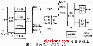
Abstract: According to the 1553B data bus protocol and its interface technology requirements, a 1553B bus interface card based on PCI local bus is designed. The system uses PL905's PCI9052 and DDC's 1553B protocol chip BU-61580, through the FPGA chip EP1C12B for PCI protocol and 1553B protocol conversion, using DSP controller TMS320F2812 as the master unit of the lower computer, and compiled the interface card driver , realizes the conversion of 1553B bus and PCI bus. Key words: PCI local bus; 1553B bus; bus interface card; data bus protocol In the early stage of the development of avionics systems, various simulation experiments were usually carried out on the ground based on microcomputers. This makes the development and innovation of interface boards for various simulation systems a key point in the development of avionics systems. The main task of the interface board is to realize the communication function between the data bus of the avionics system and the data bus of the PC, which enables the PC to simulate the actual subsystem attached to the data bus of the avionics system. The PCI (Peripheral Component Interconnect) bus, which is a peripheral component interconnect bus, is an advanced high-performance 32/64-bit address data multiplexed local bus that can support multiple sets of peripheral devices at the same time. The PCI local bus is not subject to the processor, provides a bridge for the central processor and the adjustment of peripheral devices, and can also serve as a traffic commander between the buses to improve data throughput, with support for linear burst transmission and minimal access delay. It adopts bus master control and synchronous operation, and has strong compatibility. This paper designs a PCI bus-based interface board, which serves the MIL-STD-1553B bus and writes its driver under Windows. 1 1553B bus protocol MIL-STD-1553B is a military standard for data bus electrical characteristics and protocol specifications. This standard specifies the technical requirements for digital command/response time-division multi-channel data buses within the aircraft, as well as the operation of multiple data buses. The format and format of the information flow on the bus as well as the electrical requirements. Its role is to provide a medium for transmitting data and information between different systems. The 1553B data bus performs data information transmission in an asynchronous, command/response manner. It is a duplex communication method. It has three terminal types: bus controller (BC), remote terminal (RT), and bus monitor (BM). ). BC is the only terminal on the bus that is scheduled to perform setup and start data transfer tasks. BC controls the transfer of all data information on the data bus. There is only one BC on the bus at any time. RT is the interface of the user subsystem to the data bus, which extracts data or absorbs data under the control of the BC. The MT "monitors" the transfer of information on the bus to complete the recording and analysis of the data source on the bus, but it does not itself participate in the communication of the bus. The information transmission modes between terminals are: BC to RT, RT to BC, RT to RT, broadcast mode and system control mode. The information flow on the 1553B data bus consists of messages. A complete message consists of three types: command word, data word and status word. The word length of each word is 20 b, the first 3 bits are sync headers, the valid information bits are 16 bits, the last bit is the parity bit, the odd parity is used, and the message word is modulated by the Manchester II code. All message formats are based on the three word types described above. 2 system design The system design is divided into two parts: the design of the hardware circuit and the design of the software driver and application. 2.1 system hardware design The complete hardware circuit structure of the system is shown in Figure 1. It mainly includes 1553B bus interface module, PCI bus interface module and logic control module. The system design mainly realizes the communication between the 1553B bus and the PCI bus. Because the bipolar differential signal is transmitted on the 1553B bus, level conversion and corresponding modulation and demodulation are required for the transmitted or received signal, 1553B bus interface. The module is used to complete the organization and encoding or decoding of the data. The PCI bus interface module completes communication between the interface card and the host computer. The dual port RAM acts as a data relay for the two modules, and the logic control module connects the two modules into one system. The host computer stores the data to be sent into the dual port RAM through the PCI bus interface module, and the logic control module sends the data to the 1553B bus interface module according to the communication protocol, and the 1553B bus interface module organizes and encodes the data, and sends the data to the 1553B main. On the bus; or the 1553B bus interface module receives data from the main bus, decodes it, and stores it in memory. Then inform the host computer, the host computer retrieves the data from the memory through the PCI bus interface module and the status information of the current 1553B bus operation. 2.1.1 1553B bus interface module design The 1553B bus interface module mainly includes a 1553B protocol chip, an isolation transformer, and a clock crystal. The 1553B protocol chip uses DDC's BU-61580. The chip contains two low-power dual-ended transceivers, protocol logic, memory management logic, processor interface logic and 4K & TImes; 16 b built-in shared static RAM and direct-oriented main processor The cache interface is composed of up to 64K & TImes; 16 b of external RAM. The protocol chip is connected to the 1553B main bus via a stub. An isolation transformer is required between the protocol chip and the stub. The isolation transformer isolates the 1553B main bus from the interface card DC to prevent noise generated on the interface card from affecting the signal on the 1553B main bus. The BU-61580 integrates the BC/RT/BM integrated design. The configuration register of the BU-61580 can be programmed to set the working mode of the system. For example, in this system, the bit 15 of the register 1 is configured by software programming BU-61580. For logic "1", bit 14 is logic "0", which enables BU-61580 to operate in RT mode. The memory management mode is optional and is a major feature of the RT of the BU-61580. In order to facilitate the access of the lower computer processor to receive valid and complete data blocks from a given address, to ensure the highest degree of consistency of data sampling for the processor, the RT mode memory management adopts double buffer mode. The received broadcast message can be selectively decomposed into non-broadcast messages. The specific implementation method is to provide two 32-bit data blocks for each received message, one for activation and the other for stop. After the current command ends, BU-61580 automatically switches the active area and the stop area of ​​the data block of the subaddress, so that when the command is sent to the same subaddress, if the data is valid and the double buffer is allowed, the data is saved to another data. In the block, the previous data will not be overwritten. In terms of connection with the lower computer, the interface configuration of the BU-61580 adopts a 16-bit buffer mode, which provides a direct shared RAM interface to the lower computer. In this mode, the data and address bus of the BU-61580 is isolated from the bus address of the host, and the addressing space of the BU-61580 is limited to the range of 4K words of its internal RAM.
Our LED Display have high Brightness even under sunlight;Good waterproof IP65 for front and IP54 for rear,anti-corrosion,antifogging,long life span>100000Hours;The brightness of our led dsiplay is up to 6500CD, Long view distance from 100M away;The LED module is made with high quality Epistar leds keep high quality, low lighting decay, energy saving;Brightness of led display can be adjusted automatically according to different surrondings,can be set to open and close the screen on fixed automatically;LED Display can be fixed on the wall, on the street, on top of building,or be hung for rental to meet the request of live broadcast, live meeting, banquet, party, etc, to display the content what you want, by video, graphics, antimation etc, connect with PC computer or network, also can remoto control with asynchronous system;LED display Cabinet size and materials can be customized according different projects.
Key Feature:Soft mask and soft top cover design to protect player;Slope design mask to make sure wider viewing angle;0~30degree adjustable panel design;High color fidelity and uniformity;Low consumption and long lifespan;Excellent thermal management;Excellent waterproof structure;Wide viewing angle;Easy maintenance.
Perimeter Led Display,Led Display Board,Led Display Screen,Digital Display Board Shenzhen Bako Vision Technology Co., Ltd. , http://www.rentalleddisplays.com