The advantages of the solution of motorcycle engine starter lithium battery, compared to the traditional Lead-Acid Battery, motorcycle special Starting Lithium Battery in addition to high energy density, there are the following advantages:
1. More environmental protection
Lead-acid batteries are polluted in the production process and may cause pollution if they are not recycled properly. Lithium batteries are green and environmental friendly.
2. Longer service life.
3. Low self-discharge rate, less than 10% per month, lead acid battery can reach 30%.
Motorcycle Starting Lithium Battery Starting Lithium Battery,Rechargeable Motorcycle Battery,Motorbike Starter Battery,Motorcycle Starting Battery Deep Cycle,E-motor Starter Battery,Motor Scooter Lithium-ion Battery Shenzhen Enershare Technology Co.,Ltd , https://www.enersharepower.com
Among the more challenging tasks undertaken by sensor designers is the design and manufacture of reliable, robust piezoresistive sensors for the automotive market. Through years of trial and error, these designers have developed practices and techniques that have proven useful again and again for automotive applications. To enlighten and inform those who work with this technology (which addresses the leading volume user for piezoresistive sensors), the following discussion reveal several tricks of the trade.
As a rule, 80% of the final cost for a product is established in the first 20% of the design effort. Thus, understanding the necessary design practices beforehand can minimize cost and improve your success in designing robust PRT pressure sensors for the demanding automotive environment.
If you've never designed such sensors before, the first task is to open the hood of a recent-model vehicle (your own, perhaps) and have a good look at the engine compartment. That nest of wires, hoses, connectors, and engine is one of the most severe environments a sensor can have. Consider the thermal shock to an engine-mounted sensor operating above 100 ° C and sprayed suddenly with slushy, salty water at 70mph. Other properties of this environment are just as severe: Temperature: -40 ° C to + 125 ° C (to + 150 ° C for engine-mounted sensors) Vibration: Severe to extreme Sensing Media: Fuels (mixed blends), oil, brake fluid, transmission fluid, noxious vapors, etc. External Media: Water and saltwater spray, oils, brake fluids, solvents, fuels, etc. Thermal Shock: High-temperature operation plus frequent cold-water splashing EMI: 2MHz to 2GHz radiated exposure at 200 volts per meter
Sensors located within the passenger compartment have much less exposure to fluids and solvents but are subject to low temperatures, water, and EMI: Temperature: -40 ° C to + 85 ° C Vibration: Reduced levels Sensing Media: Air typically External Media: Water spray Thermal Shock: Reduced rate of change EMI: 2MHz to 2GHz radiated exposure at 200 volts per meter
For either environment, the sensor should have the following: Reliability: 100% operational, every time, all the time Lifetime: 10 to 15 years, sometimes expressed in terms of mileage (100,000-150, 000) as well Low Cost: Automotive is among the most cost-sensitive of markets 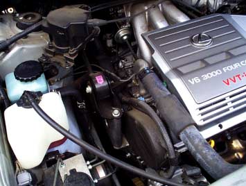
Figure 1. Typical automotive under-the-hood environment.
To ensure that a sensor will meet customer expectations for performance, its specification and related test documents should attempt to capture representative stresses and operating conditions. You should read and comprehend these documents, but remember they are only a best attempt to represent the world in which the sensor lives. Successful designs are based on proven concepts, materials, and circuits. Any connector under the hood, for example, represents decades of engineering effort in design, materials, and production technology. Similarly, the sensors accepted for use in late- model production vehicles only a couple of years ago are available for your review. You can study the technology used, the materials employed, and even the assembly techniques.
Automotive technical repair guides identify the sensors and wiring for most of today's vehicles. For example, vehicle shop manuals for late-model vehicles are available from most dealerships and auto-parts stores (Figure 2). They include drawings, photos, and wiring- voltage levels. You can buy a sensor from an auto-parts retailer, take it apart, study it, and ask yourself why it's made the way it is. Talk with automotive-design experts in your own organization, and try to distinguish among their opinions, rules of thumb, hard evidence, and data. Also, consider what new requirements the customer is asking for, what performance, cost, or reliability gains the customer is trying to realize, and whether or not these requirements represent a logical progression from what he or she is currently doing. This orientation may open your mind and lead to innovative thinking "out of the box." 
Figure 2. Shop manual showing wiring, connector, and pinout information.
In resolving problems in an existing design, you can benefit from rereading the specifications and understanding the operating environment. Several specifications are important for a typical automotive sensor (Figure 3). Is the problem related to a particular specification or test? If possible, generate an exact description that focuses your investigative effort. Be specific, and include data that shows good versus bad or issue versus no issue. Interesting anomalies and other artifacts that distract your efforts should be assessed for relevance and binned accordingly. That is, they should be saved and incorporated in the investigation, tagged as unknown, or simply tossed aside for a later investigation. The basic reasons for concern with an existing device involve design, manufacturing, and spec-versus-usage issues. 
Figure 3. Each sensor has specifications detailing the expected operating characteristics and environmental factors.
If the design isn't solid, it may not support the customer's expectations. For example, a die-attach adhesive with reduced adhesion at an elevated temperature may not provide sufficient strength during vibration to hold the die in place, or a circuit design may have insufficient tolerance for electrostatic discharge (ESD) during vehicle assembly or service. In either case, the system can fail in the field after passing its qualification and design-validation stress tests. Remember the statistics: A few select devices were tested for design robustness , but hundreds of thousands or millions were produced and field-tested. Most design issues can be avoided with a careful design review and reasonable simulations.
A key discipline in sensor design is identifying all the significant characteristics, meaning those that result in a perfect function if implemented within specifications. Such characteristics should be tracked during manufacturing using statistical process control. For a stable manufacturing process, no testing is required if you can ensure that each significant characteristic is within the limits set by statistical process control (SPC). SPC limits are quite different from specification limits. If the significant characteristics are within spec, then testing the sensor is simply a waste of time.
Practical considerations sometimes force the testing of sensors. Calibrating a sensor for pressure and temperature performance is usually more cost-effective than specifying every subassembly to the degree necessary to enable blind assembly and shipment. (Manufacturing never reaches a state of complete flawlessness, regardless of the level of continuous improvement applied.) Knowing the significant characteristics and tracking them with SPC reduces the level of test and calibration necessary, thereby improving the cycle time, yield, and (ultimately) cost.
Missing a solder joint, improperly mixing a multipart epoxy, or installing an out-of-spec subassembly can undermine the best of manufactured devices by blocking the full intent of its design. Because such manufacturing issues can arise thousands of times per day or even per hour, they compel design, product, and process engineers to remain at the manufacturing plant overnight and during the weekends. Time to resolution is of the essence. Thousands of assembly employees are waiting for each component downstream in the vehicle assembly line, and stopping the flow can cost upwards of a million dollars per day.
An executive at a major automotive supplier said, "For every bad component returned from the customer, there are a dozen more already in the manufacturing bone pile." "Bone pile" is the fallout from test and inspection during manufacturing, and failed parts are simply those with testable parameters outside the test limits (test limits include the specification limit, less the guard bands for gauge and repeatability).
How many devices encroached on the test limits but did not go over the edge? More importantly, why did they encroach in the first place? What changed? W. Edwards Deming made a career of asking these questions, and he revolutionized manufacturing by integrating it with statistical process controls [1]. Parts close to the edge limit differ from the norm and possibly differ in some way from the design intent. Is that change or difference stable? Will it change later with time or temperature and cause failures in the field ? If every component that failed a test or inspection could be analyzed to find the root cause of its failure, then by correcting the root causes you can achieve a robust and fine-tuned manufacturing process. Every component in the bone pile represents a story of process variances, material variances, and yet-undiscovered significant characteristics.
Other failures involve the product's definition versus its actual use. If, for example, a sensor specified to operate at 0-50psi is exposed to 60psi in practice, then its failure can be attributed to a poorly defined specification. In a more subtle case, a sensor is specified to operate in the presence of automotive gasoline and methanol. The design validation test includes exposure to gasoline and to methanol under defined conditions of time, temperature, and so forth, but the sensor fails in the field from an apparent exposure to gasoline. In fact, the exposure was to a blend of methanol and gasoline, in a ratio that proves more detrimental to materials than does gasoline or methanol alone. Thus, the specification and test definition that attempted to capture real-world conditions were flawed or worded improperly. The sensor met its own specification, but not the customer's expectations.
Because the many cases of spec definition versus usage are difficult to resolve late in a sensor's design cycle, you should read the specifications and test requirements, noting the actual intended environment of the sensor. For each specification item and test condition, ask yourself why it is included and what actual condition of operation is being addressed. What is the result or the implication of not meeting this specification?
To resolve design and manufacturing issues, embrace the eight-discipline (8-D) problem-solving technique. The 8-D process was developed years ago by a major automotive manufacturer, with the goal of providing an effective means for determining root causes and corrective actions. These are the eight disciplines: Problem description Containment actions Root cause Verification of root cause Permanent corrective actions Verification of permanent corrective actions Recurrence prevention Congratulations to the team! This problem-solving technique forces the removal of personal opinions and "gut-feel "statements, and brings in facts and data. The Quality Control Executive Director at Ford's Electronic Division was renowned for saying in 8-D review meetings," In God we trust; all others bring data. "It works. Keep the problem description clear and concise, to the extent of listing the serial numbers for affected units or vehicles. If immediate adjustments to process or design are employed as a temporary means to maintain quality shipments, list them as containment actions. Containment actions will be removed and / or supplemented with permanent corrective actions as soon as the PCAs are available.
The root cause will be a final and concise statement about what design, manufacturing, or specification-versus-usage issue produced the problem. Before the permanent corrective actions are released into production, a verification plan must be developed and executed as part of the verification of permanent corrective actions sequence. Recurrence prevention is critical in preventing history from repeating itself.
Finally, congratulate your team. Simple as it is, this step is the one most often overlooked and ignored. It provides two important results: The team is recognized for having identified and resolved a nontrivial issue, and the congratulations signal a closure of work on that issue, a disbanding of the team, and permission to return to normal duties.
This problem-solving process is an interesting journey of discovery regarding your sensor product and manufacturing process. If you keep an open mind to the possibilities and are confident enough to admit you don't have all of the answers all the time, then each problem can become an interesting educational experience.
Physicist Richard Feynman, winner of the Nobel prize, summed up the pleasure of finding things out as follows: "The ... thrill, the ... awe, and mystery come again and again when we look at any problem deeply enough. With more knowledge comes deeper, more wonderful mystery, luring one on to penetrate deeper still. Never concerned that the answer may prove disappointing, but with pleasure and confidence we turn over each new stone to find unimagined strangeness leading on to more wonderful questions and mysteries— certainly a grand adventure! "[2].
When it comes to PRT sensor materials (silicone-gel and other protective coatings for sense elements and ICs, and die-attach epoxies), a few comments are in order. These materials surface again and again in sensor manufacturing. Their use requires knowledge of their initial properties, extended-life properties, and precautions for handling and mixing. A typical PRT sensor assembly diagram is shown in Figure 4. 
Figure 4. Cross-sectional view of a typical PRT-based pressure sensor.
Die-attach epoxies come in many varieties and compositions. Those commonly used for PRT sensor mounting include soft-mount rubber-based adhesives, cyanoacrylate-based adhesives (with conductive silver-flake filler or nonconductive SiO2 filler), two-part epoxy blends, and silicone-based adhesives. Properties unique to each material address the issues of mechanical stress, temperature, chemical reactivity (or inertness), ease of manufacturing, and cost. The required chemical immunity depends on whether the die-attach is exposed to the ambient environment and its contaminants or to the media whose pressure is being measured. Temperature should be considered not only during operation but also during manufacture, storage, shipping, and the next level of assembly. Often the most critical parameter is mechanical stress imparted by the die -attach material to the PRT element.
Concern is directed not only to the different temperature coefficients for die-attach, substrate, and PRT elements, but also to the many silicone and epoxy-based materials that exhibit one of two different mechanical properties according to temperature. The material in question makes a transition between these properties at the glass-transition temperature Tg [3]. Materials above this temperature tend to be stiffer, with (perhaps) a reduced thermal-expansion coefficient. Below it, they tend to be softer and suppler.
This property is usually apparent as a bow or curvature in the offset or sensitivity-versus-temperature measurement (Figure 5). It becomes apparent when generating a temperature-step profile from the lowest to the highest temperature. Because any kink or inflection in the curvature indicates change in a material property, you must, in effect, design with two different materials. As if that isn't enough, the Tg for two-part epoxies depends on the ratio of the two parts being mixed. Thus, material properties for the final design are a function of the two-part measuring and mixing process. 
Figure 5. Sensitivity can change as materials pass through the glass-transition phase, or Tg.
Protective coatings for sense elements and integrated circuits impart the same property characteristics as do the die-attach materials described above, but with different effects. Protective coatings in contact with the sensing diaphragm can cause hysteresis with applied pressure, hysteresis with temperature, sensitivity and offset changes with temperature (above and below Tg), output drift with time, and output creep.
Silicon has wonderful mechanical properties for the manufacture of reliable and repeatable sensors, but the introduction of die-attach materials and protective coatings can degrade the sensor's performance. To counter this effect, you should know how the material can be altered in manufacturing by variations in the mix ratio, the effects of aging, exposure to air prior to curing, the cure time and temperature, and so forth. Once in a prototype, the chosen material will likely be different from that used in the one-millionth sensor produced.
Some simple hints can make the electronics portion of your sensor design more robust. In general, a PRT sense element is mounted on a substrate, which in turn is mounted to a housing or sensor body (Figure 6). Ducts within the housing guide a fluid media to the active portion of the PRT element. The substrate contains the signal conditioning IC (shown as a die in this case) and several discrete electrical components. It also provides electrical paths to the connector, to receive power and give access to the output signal. The connector is typically a 3-wire type that carries a voltage analog of the pressure being measured. Basic circuit-layout principles give the best performance for a given schematic design: Keep the electrical-wiring connections between the IC and the PRT sense element as short as possible. Do not intermingle the sense element's printed wiring traces with others, especially with digital-clock traces and analog OUT traces. Keep a decoupling capacitor of 0.1µF (or rec ommended value) as close to the IC as possible, with minimal printed wiring interconnects. Fill all remaining printed wiring surfaces with ground plane. Place the ESD / EMI capacitors as close to the connector pins as possible. If the circuit floats within a conductive housing that is electrically connected to the printed wiring circuit, connect the case to circuit ground with a resistive path. For all ICs, tie the unused inputs to VDD or GND as appropriate, either directly or through a resistor. Buffer the power input with a low -impedance resistor and capacitor, as close to the connector as possible. If possible, combine this filter capacitor with the ESD / EMI capacitor. Protect the passivation layers for the IC and sense element. Any compromise of the IC passivation is reason to scrap the assembly. If possible, ground the IC-mounting paddle with a conductive die-attach material. If possible, electrically insulate the sense element from the case or pressure port. 
Figure 6. A typical pressure-sensor assembly.
Debugging analog sensor circuits is a comprehensible art if you are willing to devote the time. Most sensor anomalies can be resolved quickly: Check the power supplies. Check the clock. Check the memory. Check where the test equipment is referenced and grounded. Often an apparent sensor anomaly is actually a good sensor operating in a bad environment. To be certain that the problem lies within the sensor itself, you can save hours of time and frustration by checking and double-checking the sensor's circuit-debugging procedures can be found in the book Troubleshooting Analog Circuits [4].
In debugging one faulty sensor (fallout from the line, for example), you can have confidence in knowing that several thousand supposedly identical units have worked just fine. When each component is connected and operating properly, you can therefore be sure the device will also work properly. This assurance is absent when debugging a first-time prototype, in which no circuit like it has ever been produced or demonstrated to work. The challenge, therefore, is to note how the sensor at hand differs from its several thousand predecessors.
Sensor repeatability is everything. No amount of electronics can correct a sensor whose responses to temperature and pressure are unpredictable. Several tricks for uncovering the causes of nonrepeatability in sensors have been proven time and again. You must decide, however, which ones apply to your sensor assembly: Slow temperature-step cycling High-temperature soak High-temperature soak, pressure hysteresis check Power-supply rejection test over temperature By stepping temperature in small increments from the lowest to the highest extreme, slow temperature-step cycling measures the variation of offset and span over temperature. Most sensors are tested at + 25 ° C, then at -40 ° C, then at + 125 ° C (or + 85 ° C), and once again at + 25 ° C. Called the tri- temperature test, this procedure assumes that the sensor exhibits a smooth and continuous behavior at the intermediate temperature points.
But what really happens in between? Try this test on any good sensor: Cycle the temperature from room temperature to cold, to hot, to cold, to hot, and back to room temperature in 15 ° C increments, measuring the sensor response at each level. If the sensor is rated -40 ° C to + 125 ° C, try temperature cycling beyond these limits, say from -55 ° C to + 150 ° C. Does offset and span follow the same curve on each cycle, or does each cycle produce a different curve? This test exceeds the sensor's specified operating range, but it would be nice to know that no sudden, catastrophic failures occur just outside that range.
With regard to reliability, the behavior of sensor outputs at the extremes is just as interesting as a failure. Do the curves exhibit a significant inflection near or just beyond the operating temperature limit? What material or electrical property has changed or become dominant to cause this inflection? Inflections often begin within the normal operating range, indicating that a polymer material entered the glass phase via the glass transition temperature described earlier. Were alternate properties (temperature coefficient, Young's Modulus, etc.) considered in the original design? When the device comes out of the glass phase, does it return to its original stress level and / or position? If not, then hysteresis with temperature may be present in the output.
The high-temperature soak test checks material stability. Starting at 25 ° C, verify sensor operation, then monitor the sensor output while quickly running the temperature to its highest operating level or beyond. Record the output for several hours while maintaining the high temperature. Output changes during this hold time indicate either an output variance due to thermal gradients across the sensor as the assembly comes to equilibrium at the elevated temperature (not so interesting) or material creep (much more interesting), which occurs when materials respond to stress by relaxing or moving to a less stressed condition.
Which material is creeping? Check the plastics and polymers. To determine which is the culprit, build a sensor using a different material (such as a protective coating), one using more or less of the same material, or one that lacks the suspect material . Then, rerun the test on the modified unit and (ideally) a control unit as well, to see if the property changes.
The test of high-temperature soak with pressure-hysteresis check is similar to the above, but it monitors the output while cycling pressure from minimum to maximum, rather than monitoring the output over time. Does the pressure output signal follow the same curve each time ? If not, some material may be relaxing or creeping due to the applied pressure. As a final test, set the pressure at maximum and hold it steady while returning the device to room temperature (or lower), and then reduce the pressure to zero . Does the output settle immediately to the zero value? Does it take several hours, or days, to return to the zero value recorded at the start of the test? If so, check the polymer materials. In addition, consider any mechanical assemblies in which two dissimilar materials are in contact with each other, causing a friction-slip condition.
For the test of power-supply rejection over temperature, simply cycle the supply voltage from minimum to maximum at each of several different temperatures. Highest, lowest, and room temperatures are generally sufficient. Is the output change due to supply-voltage change the same at each temperature? Is the output significantly noisier (or quieter) when hot or cold? The IC will have different power-supply-rejection characteristics at various temperatures, but external capacitors (monolithic, tantalum, electrolytic) have pronounced effects on the base values of these characteristics. The circuit design should account for these factors by analyzing worst-case effects such as the variation of component values ​​over temperature.
This test offers an opportunity to explore circuit properties such as the low-voltage operating point and startup-reset operation. At each temperature, slowly dial down the supply voltage until the sensor ceases to work. When it ceases to function, dial the voltage back up to its normal operating range and see if the circuit recovers and begins operating. This procedure tests the design for robustness to power-supply anomalies over temperature. On the other hand, a check of high-voltage operating capability is not recommended, because that test is usually a sure way to let smoke out of an IC.
The last point on reliable sensor production concerns change, which is arguably the main problem in high-volume automotive manufacturing. Because change generally begets trouble, it is dreaded and feared by most automotive manufacturing engineers with more than a few years in the business. Small changes that seem insignificant can bring to a halt the daily multimillion-dollar operation of a vehicle body and assembly plant. To illustrate this effect, the mathematician Benoit Mandlebrot proposed that a disturbance introduced by the wings of a single butterfly in China might cause a hurricane halfway around the world.
Be sure to create a verification plan for any proposed change in manufacturing, materials, or components. The verification plan outlines tests to be conducted in demonstrating the absence of adverse impacts. It should replicate all downstream vehicle-assembly and test operations, as well as vehicle road tests.
The common denominator for many change decisions is cost reduction. When change for the purpose of cost savings is forced on a well-designed product, without fully comprehending or verifying the consequences, the result can be a disaster. Nothing can beat the cost performance of a product that is well designed (meaning that it represents a cost-effective selection and evaluation of materials and processes) and produced in a well-defined manufacturing process running at high yield. The best advice for a cost-reduction strategist is to focus on the next-generation design and leave the existing product alone. References Walton, M. 1986. The Deming Management Method. Perigee Books.
Feynman, Richard, 1999. The Pleasure of Finding Things Out. Perseus Books, p.144.
Higgins, RA 1994. Properties of Engineering Materials. 2nd ed. Industrial Press Inc., pp. 296-298.
Pease, Robert. 1991. Troubleshooting Analog Circuits. Butterworth-Heinemann. A similar version of this article appeared in the April 2001 issue of Sensors magazine.
Abstract: Design and manufacturing methodologies for automoTIve pressure sensors to create robust sensors for this demanding environment. Material property selecTIon and circuit design principles are covered. Cost sensiTIve designs that meet the range of automoTIve specifications and requirements are discussed. Analyzing defective units and manufacturing fallout as a tool to improving the design and manufacturing process.