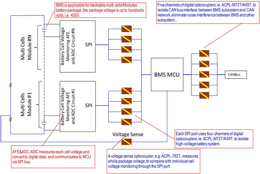
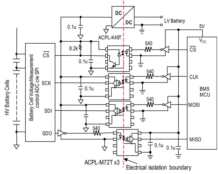
Due to transients, extreme temperature environments, and other factors, there are many design challenges for circuits and subsystems used in automobiles when switching from gasoline-fueled vehicles to hybrid-electric or full-electric vehicles. High-voltage battery arrays and connections to various subsystems, such as transmission systems and other high-power power systems, must be isolated to keep the battery system "floating", avoiding leakage currents or high voltages reaching low-voltage systems and automotive enclosures . The charger on the plug-in electric vehicle receives 240V high mains voltage and draws high current during nighttime charging, so it is very important to resist the instantaneous high voltage protection. Currently, automakers are seeking standardized battery management. System (BMS, Battery Management System) so that battery arrays up to 1000V can be provided. In order to achieve the necessary level of isolation, opto-isolators have become the industry standard for providing high electrical isolation and high noise immunity, and consuming lower power than using transformer coupling to provide isolation. The battery subsystem uses a large number of battery cells. High power noise and load are particularly difficult due to large transients caused by battery charging currents. In addition, it is important to monitor the voltage of each cell in the array in the design of the battery array itself and the charging subsystem. It must be such that failure of a single cell does not cause the entire array to cease operation or overload the charging system. A typical battery array in an electric vehicle consists of a plurality of battery modules, each module typically containing a number of individual battery cells and special circuitry for monitoring the battery cells in the module. The entire array can provide a voltage output of hundreds of volts, typically above 400V. The monitoring circuit takes the battery voltage and other parameters, digitizes the collected data and transmits it to the microcontroller (MCU) that manages the battery system through the Serial Peripheral Interface (SPI) bus. Please refer to Figure 1, followed by micro The controller sends control signals to various subsystems in the car through a controller area network (CAN). In order to isolate the battery subsystem and the microcontroller, the opto-isolator is used to receive the serial data sent by the battery unit monitoring circuit SPI output and provide a physical barrier, mainly by means of the separation of the LED emitter and the photosensitive receiver, and the isolation of hundreds of volts can be Avoid transients, electrical noise, and other factors that can damage the system, allowing the battery system to be “floating,†ie, not directly connected to the car body. In addition, current leakage can be minimized by the absence of a car body. . Figure 1: A typical battery management subsystem requires multiple optocouplers to provide isolation between the SPI bus and the microcontroller and between the microcontroller and the CAN bus. Different types of optocouplers are used in the battery subsystem to provide different levels of voltage isolation and performance to meet the performance requirements of different parts of the system, please refer to Figure 2. For example, the SPI interface typically operates at data rates in excess of 1 MHz and requires an operating temperature range of -40 ° C to +125 ° C. These requirements result in the use of ACPL-K49T and other similar optocouplers. To isolate low-speed chip select signals, higher-speed optocouplers such as the ACPL-M72T or other similar products can be used as faster SPI signal lines on each battery monitoring circuit, such as serial clocks, serial data inputs, and strings. Line data output, etc., please refer to Figure 3. Figure 2 The four signals on the SPI connection port on the battery monitoring circuit use opto-isolators to ensure that no high-voltage pulses are passed from the battery array to the low-voltage microcontroller. The ACPL-K49T is a single-channel optocoupler with an LED emitter, isolation barrier, photodiode receiver and a transistor amplifier. It is very simple to structure. Please refer to the left side of Figure 3. This device can handle data rates up to 20Kbits/s. Provides 30kV/μs high common mode rejection (CMR) and low LED drive current of 4mA at VCM=1,500V. Conversely, ACPL-M72T has a more complex receiver side structure. The photodiode is coupled to the transimpedance amplifier and the output driver circuit of a voltage comparator to better handle the driving of the SPI bus. Please refer to the middle of Figure 3. This optocoupler can operate at data rates up to 10 Mbits/s with propagation delay. The maximum is 100ns and the current consumption is only 4mA. Rainproof Yangdong Diesel Generator Single Phase Ac Generator,Rainproof Yangdong Diesel Generator,Yangdong Rainproof Diesel Generator,Yangdong Rainproof Diesel Generator Set Jiangsu Lingyu Generator CO.,LTD , https://www.lygenset.com