Almost all of the outdoor led light use of large areas of lighting can be seen as led flood light. The led flood light is a fixture that specifies that the illuminance is higher than the surrounding environment. Also known as spotlight. Often it can target any direction and have a structure that is not affected by climatic conditions. Mainly used for large-scale workplace mine, building contours, stadiums, overpasses, monuments, parks and flower beds, etc. The angle of the exit light beam is wide and narrow, ranging from 0 ° to 180 °, Narrow called the searchlight.
Outdoor LED Flood Light features:
1, the use of internal and external anti-seismic structure design, effectively solve the strong vibration caused by falling off the lamp, lamp life shortened, stent fracture and other issues. This is important for outdoor led flood light.
Outdoor led flood light picture show:
Outdoor LED Flood Light Outdoor LED Flood Light,Waterproof Outdoor LED Flood Light,High Power Outdoor LED Flood Light Shenzhen Mingxue Optoelectronics CO.,Ltd , https://www.led-lamp-china.com
IntroducTIonIn today's increasingly complex embedded systems, a user interface is a necessity rather than a convenience. To facilitate this design requirement, engineers must first determine the complexity of the interface, which can range from a simple LED to more complex character or graphic LCDs.
The LED—A Basic InterfaceThe simplest applicaTIons may only require on / off-type LEDs for displaying status information. In that case, the LEDs can be controlled directly by a general-purpose I / O pin capable of sourcing or sinking the necessary current required for lighting the LED, typically between 2mA and 10mA. To determine the source / sink current capabilities of the microcontroller, you should check its datasheet for VOH or VOL values. Often these values ​​are given for a specific condition, and it may be necessary to interpolate the values ​​for a higher or lower current.
Figure 1 shows a LED circuit commonly used with a microcontroller, the MAXQ2000. In this case, the resistor, R, must be sized to limit the current through the LED to 4mA. To calculate R's value, assume that the LED drop is typically 2.0 V (confirm this by checking the LED data sheet) when turned on. The MAXQ2000's low output voltage is specified to be a maximum of 0.4V. Therefore, the voltage at the base of the resistor is 0.4V + 2.0V, or 2.4V . Using Ohm's law:
R = (3.3V-2.4V) / 4mA = 225Ω. 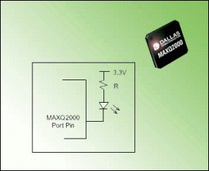
Figure 1. LED circuit that interfaces to the MAXQ2000 microcontroller.
More Informative—and Complicated—InterfacesAlthough an LED provides simple status information, many new embedded system designs require a more complicated and informative user display. System status, user settings, measured values, and other types of data are not easily communicated with a simple LED . The designer has several options available for this broader range of information, including graphic and alphanumeric LCDs.
A first consideration is the LCD driver. A basic microcontroller allows you to connect an external LCD driver through a serial or parallel interface. The primary advantage to this approach is the ability to quickly add an LCD to an existing design with very little rework to the embedded software or system schematic. There is, however, a caveat with this approach. The external LCD driver can increase both the board size and cost, while also using valuable microcontroller resources.
Newer microcontroller families, such as the MAXQ shown above, offer an integrated LCD driver. This design offers many advantages, including reduced resource consumption, smaller board space, fewer components, and lower power.
When choosing an LCD for an embedded system, there are several factors to consider. Of primary importance is the total number of characters or symbols to display. This number directly determines the total number of segments required for the LCD. Each character on an LCD is Usually comprised of between 7 to 14 segments, and the microcontroller's LCD driver controls each segment. If the application needs to display time, for example, the LCD will require four numeric characters and a colon between the hour and minute characters. For the colon, a single segment can be used. Moving beyond such a basic LDC display, many LCD manufacturers produce custom LCD versions in their devices to meet specific application requirements. A blood pressure monitor could use a heart symbol to indicate heartbeats. This special character can also be displayed using a single-segment driver. As one can see, it is easy to generate a complex user interface using a limited number of segments.
Another important design consideration is the LCD duty cycle supported by the microcontroller. Multiple duty cycles let the application support a wide variety of displays. The MAXQ2000 has integrated support for static, 1/2, 1/3, and 1/4 duty cycles, allowing display of between 36 and 132 LCD segments. In a static duty cycle, each LCD segment is driven directly from an LCD pin on the microcontroller. Consequently, in static mode the total number of segments possible is equal to the number of available segment pins (36 on the MAXQ2000-RAX). For multiplexed duty cycles, the LCD controller in the microcontroller drives multiple segments per clock cycle. As a result, multiplexed displays can suffer from a degraded video image versus a static display, because each segment is only lit for a portion of each display cycle. The viewing quality can, however, be adjusted using contrast control. In multiplexed duty-cycle operation, the denominator indicates the number of COM pins driven in a singl e cycle. In 1/4 duty-cycle mode, for example, the number of COM pins is 4 (denominator), leaving 33 total segment pins on the MAXQ2000. The total segments supported by the microcontroller increases to 33 x 4, or 132 segments. Taking these factors into consideration, a complex user interface is actually simple to create.
As 8- and 16-bit microcontroller applications expand into more complicated control applications, there is often a need to display more sophisticated or user-friendly information in the user interface. This is especially true in today's automotive dashboard electronics, medical equipment, and safety devices. Recognizing these application trends, microcontrollers that accommodate these interface needs and provide designers the flexibility to choose among a wide variety of devices will undoubtedly save design time and effort. The benefit is clearly shorter time to market with more application-specific products.
2, Outdoor flood light with high efficiency gas discharge lamp as light source, lamp life of 10,000 hours or more, especially for large outdoor unattended lighting.
3, the use of lightweight alloy materials and high-tech spray technology, the shell will never rust, never corrosion.
4, Outdoor flood light using piping and other new technology to ensure that the shell is good, sealed and reliable, waterproof and dustproof.
5, with good electromagnetic compatibility, will not cause electromagnetic interference to the surrounding environment.
6, the overall cooling of the lamp is good, can reduce the probability of failure.

Abstract: This applicaTIon note describes how the capabiliTIes of the MAXQ2000 microcontroller are ideal for driving both simple and complex user interfaces.