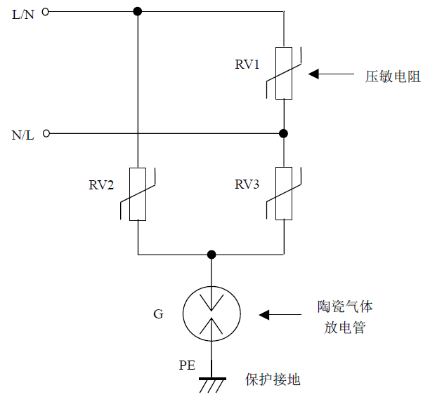
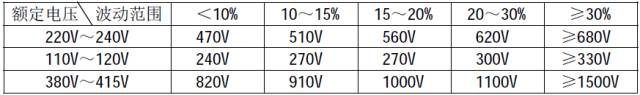
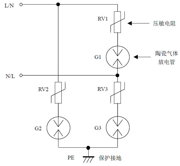
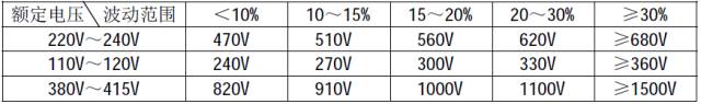
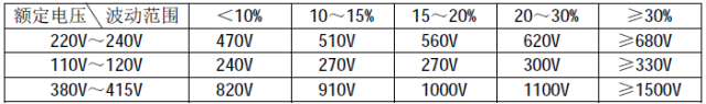
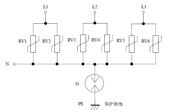
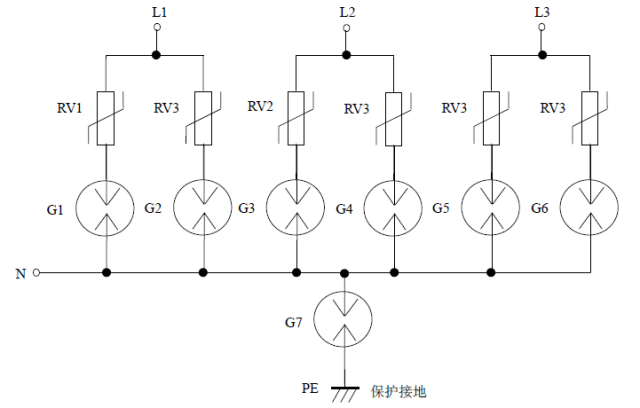
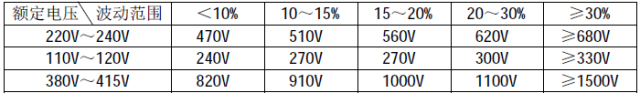
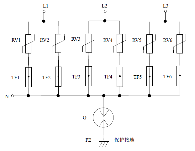
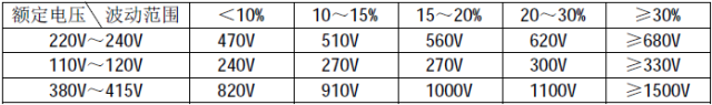
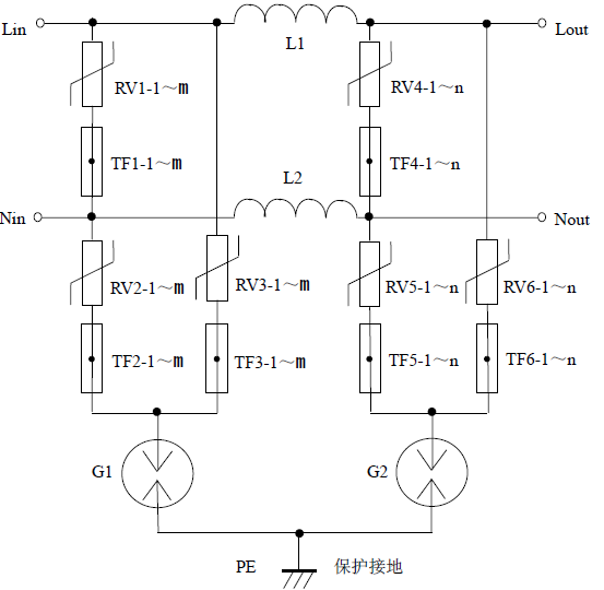
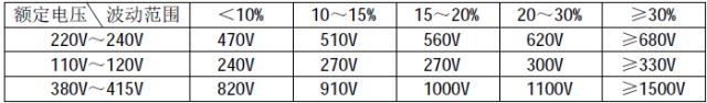
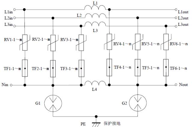
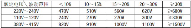
1. AC Power Supply Surge Arrester (1) Single-phase Parallel Surge Arrester Circuit 1: The simplest circuit Description: 1. Advantages: The circuit is simple, adopting a compound symmetrical configuration, providing full protection for both common mode and differential mode. L and N lines can be connected randomly. Disadvantages: The varistor RV1 is prone to fire after a short-circuit failure. It's recommended to connect a power frequency fuse in series with each varistor to prevent such failures. If the L and N lines are not reversed, RV2 and RV3 can be omitted, and the upper end of the discharge tube G can be directly connected to the N line to form a "1+1" circuit. 2. The varistor voltage value should be selected according to the table provided (choosing a higher varistor voltage increases safety and durability, but may slightly increase residual voltage). The external size and package form should be chosen based on the required flow capacity. Multiple varistors can be used in parallel (selecting parallel varistor voltages helps extend service life and ensure safety). 3. The ceramic gas discharge tube's flow capacity should be selected based on the required capacity, with a DC breakdown voltage ranging from 470V to 600V. For flow capacities ≤ 3KA, a glass discharge tube can be used as an alternative. 4. The varistor and gas discharge tube must calculate their flow capacity based on a derating value of more than 10 times the impact (the varistor is about one-third of the impulse flow capacity, while the gas discharge tube is around half of the maximum flow capacity). Original document: A variety of lightning protection circuit large anatomy.pdf Download method: Respond to "Lightning Protection" in the public number for free access Circuit 2: Safer circuit Description: 1. Advantages: This circuit uses a compound symmetrical configuration, offering full protection against both common and differential modes. L and N lines can be connected arbitrarily. There is no leakage current during normal operation, which extends device lifespan. Since the failure mode of ceramic gas discharge tubes is mostly open circuit, it is less likely to cause fires. Disadvantages: In case of a short-circuit failure in the varistor or ceramic gas discharge tube, there is still a possibility of fire. 2. The varistor voltage value is selected according to the table (choosing a higher varistor voltage increases safety and durability, though it may slightly increase residual voltage). External dimensions and package forms are selected based on the flow capacity requirements. Multiple varistors can be used in parallel (parallel varistor voltages should be selected, and each varistor should be connected in series with a temperature fuse to extend service life and ensure safety). 3. The ceramic gas discharge tube's flow capacity is selected based on the required capacity, with a DC breakdown voltage between 470V and 600V. For flow capacities ≤ 3KA, a glass discharge tube can be used instead. 4. The varistor and gas discharge tube must calculate their flow capacity based on a derating value of more than 10 times the impact (varistor is about one-third of the impulse flow capacity, gas discharge tube is about half of the maximum flow capacity). Circuit 3: Universal safety protection circuit Description: 1. Advantages: This circuit uses a composite symmetrical configuration, providing full protection against common and differential modes. L and N lines can be connected arbitrarily, ensuring safety. After a short-circuit failure, the varistor can be disconnected from the circuit, generally not causing fires. 2. The varistor voltage value is selected according to the table (choosing a higher varistor voltage increases safety and durability, though it may slightly increase residual voltage). External dimensions and package forms are selected based on the flow capacity requirements. Multiple varistors can be used in parallel (parallel varistor voltages should be selected, and each varistor must be connected in series with a temperature fuse to extend service life and ensure safety). 3. The temperature fuse is typically set at 130°C ~ 135°C, 10A / 250V, and should have good thermal coupling with the varistor. It is better to connect a power frequency fuse in series to prevent power frequency overvoltage from instantaneously breaking through the varistor. 4. The ceramic gas discharge tube's flow capacity is selected based on the required capacity, with a DC breakdown voltage between 470V and 600V. For flow capacities ≤ 3KA, a glass discharge tube can be used instead. 5. The varistor and gas discharge tube must calculate their flow capacity based on a derating value of more than 10 times the impact (varistor is about one-third of the impulse flow capacity, gas discharge tube is about half of the maximum flow capacity). (2) Three-phase Parallel Surge Arrester Circuit 1: The simplest circuit Description: 1. Advantages: It adopts a "3+1" circuit, making the circuit simple and providing full three-phase protection. Disadvantages: The varistor is prone to fire after a short-circuit failure. It is best to connect a power frequency fuse in series with each varistor to prevent this. 2. The varistor voltage value is selected according to the table (choosing a higher varistor voltage increases safety and durability, though it may slightly increase residual voltage). External dimensions and package forms are selected based on the flow capacity requirements. Multiple varistors can be used in parallel (as shown in the figure, two varistors per phase are connected in parallel, and parallel varistor voltages should be selected to prolong service life and ensure safety). 3. The ceramic gas discharge tube's flow capacity is selected based on the required capacity, with a DC breakdown voltage between 470V and 600V. For flow capacities ≤ 3KA, a glass discharge tube can be used instead. 4. The varistor and gas discharge tube must calculate their flow capacity based on a derating value of more than 10 times the impact (varistor is about one-third of the impulse flow capacity, gas discharge tube is about half of the maximum flow capacity). Circuit 2: Safer circuit Description: 1. Advantages: It adopts a "3+1" circuit, offering full three-phase protection. No leakage current during normal operation, extending device lifespan. Since the failure mode of ceramic gas discharge tubes is mostly open circuit, it is less likely to cause fires. Disadvantages: In the event of a short-circuit failure in the varistor or ceramic gas discharge tube, it may still cause a fire. 2. The varistor voltage value is selected according to the table (choosing a higher varistor voltage increases safety and durability, though it may slightly increase residual voltage). External dimensions and package forms are selected based on the flow capacity requirements. Multiple varistors can be used in parallel (as shown in the figure, two varistors per phase are connected in parallel, and parallel varistor voltages should be selected to prolong service life and ensure safety). 3. The ceramic gas discharge tube's flow capacity is selected based on the required capacity, with a DC breakdown voltage between 470V and 600V. For flow capacities ≤ 3KA, a glass discharge tube can be used instead. 4. The varistor and gas discharge tube must calculate their flow capacity based on a derating value of more than 10 times the impact (varistor is about one-third of the impulse flow capacity, gas discharge tube is about half of the maximum flow capacity). Circuit 3: Universal safety protection circuit Description: 1. Advantages: It adopts a "3+1" circuit, providing full three-phase protection, safety, and the ability to disconnect the varistor from the circuit after a short-circuit failure, generally not causing fires. 2. The varistor voltage value is selected according to the table (choosing a higher varistor voltage increases safety and durability, though it may slightly increase residual voltage). External dimensions and package forms are selected based on the flow capacity requirements. Multiple varistors can be used in parallel (as shown in the figure, two varistors per phase are connected in parallel. The varistor voltage should be connected in parallel with each other. Each varistor should be connected in series with a temperature fuse to extend service life and ensure safety). 3. The temperature fuse is typically set at 130°C ~ 135°C, 10A / 250V, and should have good thermal coupling with the varistor. It is better to connect a power frequency fuse in series to prevent power frequency overvoltage from instantaneously igniting the varistor. 4. The ceramic gas discharge tube's flow capacity is selected based on the required capacity, with a DC breakdown voltage between 470V and 600V. For flow capacities ≤ 3KA, a glass discharge tube can be used instead. 5. The varistor and gas discharge tube must calculate their flow capacity based on a derating value of more than 10 times the impact (varistor is about one-third of the impulse flow capacity, gas discharge tube is about half of the maximum flow capacity). (3) Single-phase Series Surge Arrester Single-phase universal safety protection circuit: Description: 1. Advantages: Two-stage composite symmetrical circuit, providing full protection for both common and differential modes, low residual voltage, L and N lines can be connected randomly, safe, and the varistor can be disconnected from the circuit after a short-circuit failure, generally not causing fires. 2. The varistor voltage value is selected according to the table (choosing a higher varistor voltage increases safety and durability, though it may slightly increase residual voltage). External dimensions and package forms are selected based on the flow capacity requirements. Multiple varistors can be used in parallel (as shown in the figure, m varistors in the first stage and n in the second stage are connected in parallel. Parallel varistor voltages should be selected, and each varistor should be connected in series with a temperature fuse to extend service life and ensure safety). 3. The temperature fuse is typically set at 130°C ~ 135°C, 10A / 250V, and should have good thermal coupling with the varistor. It is better to connect a power frequency fuse in series to prevent power frequency overvoltage from instantaneously breaking through the varistor. 4. The ceramic gas discharge tube's flow capacity is selected based on the required capacity, with a DC breakdown voltage between 470V and 600V. For flow capacities ≤ 3KA, a glass discharge tube can be used instead. 5. The varistor and discharge tube must calculate their flow capacity based on a derating value of more than 10 times the impact (varistor is about one-third of the impulse flow capacity, and the discharge tube is about half of the maximum flow capacity). 6. The series inductance is a hollow inductor, with an inductance of ≥20μH, and the wire diameter should be calculated based on the load current. (4) Three-phase Series Surge Arrester Three-phase universal safety protection circuit: Description: 1. Advantages: It adopts a two-level “3+1†circuit, providing full three-phase protection, low residual voltage, and safety. The varistor can be disconnected from the circuit after a short-circuit failure, generally not causing fires. 2. The varistor voltage value is selected according to the table (choosing a higher varistor voltage increases safety and durability, though it may slightly increase residual voltage). External dimensions and package forms are selected based on the flow capacity requirements. Multiple varistors can be used in parallel (as shown in the figure, m varistors in the first stage and n in the second stage are connected in parallel. Parallel varistor voltages should be selected, and each varistor should be connected in series with a temperature fuse to extend service life and ensure safety). 3. The temperature fuse is typically set at 130°C ~ 135°C, 10A / 250V, and should have good thermal coupling with the varistor. It is better to connect a power frequency fuse in series to prevent power frequency overvoltage from instantaneously breaking through the varistor. 4. The ceramic gas discharge tube's flow capacity is selected based on the required capacity, with a DC breakdown voltage between 470V and 600V. For flow capacities ≤ 3KA, a glass discharge tube can be used instead. 5. The varistor and discharge tube must calculate their flow capacity based on a derating value of more than 10 times the impact (varistor is about one-third of the impulse flow capacity, and the discharge tube is about half of the maximum flow capacity). 6. The series inductance is a hollow inductor, with an inductance of ≥20μH, and the wire diameter should be calculated based on the load current. 12V Lithium Battery,Customized lithium battery pack for drone,Lithium Cell Batteries,lithium converged batteries Shenzhen Jentc Technology Co., LTD , https://www.phenyee.com