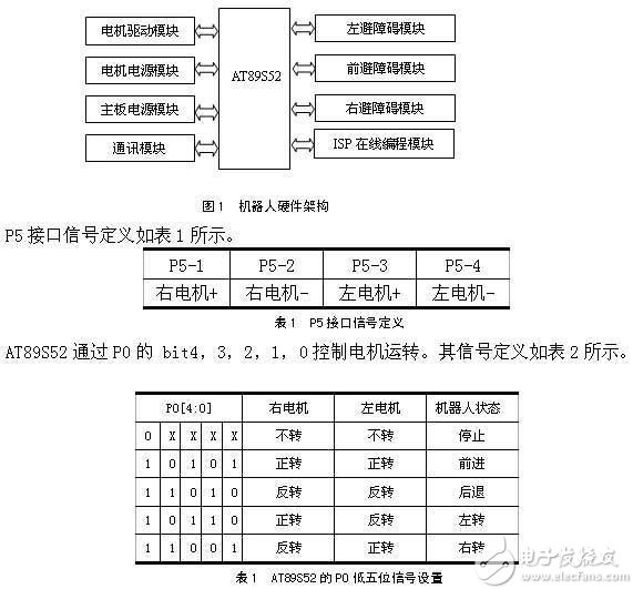
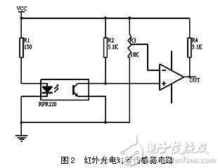
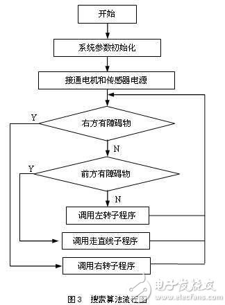
1 Introduction 2 System Hardware Architecture and Working Principle Once powered on, the sensor collects signals from the labyrinth structure, allowing the microcontroller to control the lower five bits of port P0. This enables the robot to perform maneuvers such as turning left, turning right, or moving straight, successfully navigating from the entrance to the exit of the maze. 3 System Interface Circuit Design 3.1 Microcontroller Module The AT89S52 is a low-power, high-performance 8-bit CMOS microcontroller featuring 8KB of ISP Flash memory that can be erased and rewritten up to 1,000 times. It is fabricated using high-density non-volatile memory technology and is compatible with the standard MCS-51 instruction set and 80C51 pin configuration. The device integrates a general-purpose 8-bit CPU and an ISP Flash memory unit, offering a cost-effective solution for many embedded applications. With 40 pins, 8KB of Flash program memory, 256B of RAM, 32 external I/O ports, 5 interrupt levels, 2 layers of nested interrupts, two 16-bit timers, a full-duplex serial communication port, a watchdog timer, and an internal clock oscillator, the AT89S52 is well-suited for a variety of control tasks. In the development process, a development board is used for debugging and testing. Once the system is fully debugged, the microcontroller is removed from the development board and installed into the robot’s system board. Since the robot performs relatively simple tasks, only the crystal oscillator and reset circuit are retained, while unnecessary components like the JTAG programming port are omitted. 3.2 Sensor Module The photoelectric sensor works by emitting infrared light from its emitter and detecting the reflected intensity with a receiver. For this to function properly, the surface being detected must have both black and white areas to absorb and reflect the infrared light. This allows the receiving tube to operate in either cutoff or saturation mode for accurate counting. The sensor’s detection and adjustment circuit is shown in Figure 2. Resistor R3 is used to adjust the comparator’s threshold voltage. Observing the output waveform with an oscilloscope, it appears regular and suitable for direct use by the MCU. The battery voltage drop across the circuit is also minimal, ensuring stable operation. The infrared sensor is connected to the P0.5, P0.6, and P0.7 ports of the AT89S52 through the P8, P9, and P10 interfaces on the main board. When P0.5 = 0, it means an obstacle is in front; P0.6 = 0 indicates an obstacle on the left; and P0.7 = 0 shows an obstacle on the right. 3.3 DC Motor Drive Circuit and Power Module The DC motor is connected to the mainboard’s motor drive module via the P5 interface. In this design, the L298 chip is used as the motor driver. Pins 5, 7, 10, and 12 of the L298 are connected to the microcontroller. Through programming, the microcontroller can control the forward and reverse rotation of the two DC motors. Since the microcontroller operates at around 4.8V, a VFM step-up power supply chip is used to provide approximately 5V to the microcontroller and its peripherals. 4 Software Design Module 4.1 Software Development Environment and Search Algorithm This paper uses Keil uVision 2 as the development environment, combining C and assembly language for programming. In terms of software algorithms, we consider the efficiency of the depth-first search algorithm, which increases with the complexity of the maze. However, this paper employs the "left-hand rule" (or "right-hand rule") for pathfinding, where the robot follows the wall on its left (or right) side to find the exit. Compared to the depth-first approach, the left-hand rule does not depend on the maze’s complexity, requiring no backtracking. Additionally, since the hardware precision is not extremely high, the robot doesn’t need precise control over distance or direction, simplifying the driving mechanism. To implement the algorithm, the following constraints are applied: 4.2 Algorithm Flowchart Description The flow of the maze navigation algorithm is shown in Figure 3. After the motor and sensor power are activated, the microcontroller determines the motor’s direction based on the sensor readings. If P0.7 = 1, indicating no obstacle on the right, the robot follows the right-hand rule and executes the right turn routine. If P0.7 = 0 and P0.5 = 0, it suggests obstacles on both sides, so the left turn routine is called. Otherwise, the robot moves straight ahead. This process repeats until the robot exits the maze. 5 Conclusions and Innovations This paper explores the hardware architecture of an embedded intelligent tracing robot based on the AT89S52 microcontroller. It discusses the use of the left-hand (or right-hand) rule for pathfinding, along with the implementation of the photoelectric sensor module, DC motor drive circuit, and power supply system. After extensive testing, the robot successfully navigates from the entrance to the exit of a maze without external input, guided solely by software. The innovation lies in the automatic obstacle detection using infrared sensors and the software-based control of the robot’s movement, enabling it to detect complex paths—especially useful in environments inaccessible to humans. The system is cost-effective, reliable, and responsive, offering valuable insights for the design of future smart toys. Corrugated pipe is a type of pipe that has a series of parallel ridges and grooves on its surface, giving it a corrugated appearance. It is commonly made from high-density polyethylene (HDPE) or polypropylene (PP) materials. Corrugated pipe is used in a variety of applications, including drainage systems, culverts, stormwater management, and agricultural irrigation. The corrugated design provides strength and flexibility, allowing the pipe to withstand the pressure and movement of soil and water. It is also lightweight, easy to install, and resistant to corrosion and chemicals. Corrugated pipe comes in different sizes and lengths to accommodate various project requirements. Corrugated Flexible Conduit,Split Flexible Electrical Tubing,Corrugated Tube,Bellows Tube,Corrugated Hose, Dongguan Liansi Electronics Co.,Ltd , https://www.liansisleeve.com