The 6KV/6.6KV Medium Voltage Variable Frequency Drive is a product accumulated by FGI for over 20 years. The system adopts modular design, mainly including phase shift transformer cabinet, power unit cabinet and control cabinet, etc. The Mv Vfd has the advantages of low input harmonic content and high power factor. The High Voltage Drive is widely used in pumps, fans, woodworking machinery, cement production and other industries.
6Kv And 6.6Kv Medium Voltage Drives Mv Drives,Mv Vfd,High Power Motor Drives,6Kv And 6.6Kv Medium Voltage Drives,Medium Voltage Motor Starter,High Voltage Motor Controller FGI SCIENCE AND TECHNOLOGY CO., LTD , https://www.fgi-tech.com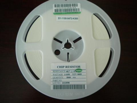 The application of surface mount technology (SMT) is now very common, and the proportion of electronic products assembled using SMT is over 90%. With the development of small-scale SMT production equipment, the application scope of SMT is further expanded. SMT is also used in the fields of aviation, aerospace, instrumentation, and machine tools to produce various electronic products or components with small batch sizes. In recent years, in addition to electronic product developers developing new products with patch-type devices, maintenance personnel also began to extensively repair SMT-assembled electronic products. The following Xiaobian describes the main parameters and specifications of the SMD resistors, capacitors, and inductors with the largest amount of application. It is for reference only.
The type of chip resistors is not uniform, and is set by the manufacturers themselves, and the models are particularly long (composed of a dozen letters and numbers). If you can correctly propose various parameters and specifications of the SMD resistor during the purchase, it can be easily selected. Patch resistors have five parameters, namely size, resistance, tolerance, temperature coefficient, and packaging.
The 1 size series chip resistor series generally has 7 sizes, which are represented by two size codes. A size code is an EIA (American Electronic Industry Association) code represented by 4 digits. The first two digits and the last two digits represent the length and width of the resistor, respectively, in inches. The other is the metric code, which is also represented by 4 digits and its unit is mm. Different size resistors have different power ratings. Table 1 lists the code and power ratings for these seven resistance dimensions.
2 Resistance series The nominal resistance is determined by series. Each series is divided by the tolerance of the resistor (the smaller the tolerance is, the more the resistance is divided). The most commonly used is E-24 (tolerance of resistance value is ±5%). The surface of the chip resistor is represented by a three-digit number, where the first and second digits are valid numbers, and the third digit indicates the number of zeros to follow. When there is a decimal point, it is represented by "R" and it occupies one significant digit. Nominal resistance code indicates the method as shown in Table 3.
3 Tolerance Chip resistor (carbon film resistor) has 4 tolerances. That is, grade F, ±1%; grade G, ±2%; grade J, ±5%; grade K, ±10%.
4 Temperature coefficient The temperature coefficient of the chip resistor has two levels. That is, w grade, ±200ppm/°C; X grade, ±lOOppm/°C. Only resistors with an F-class tolerance are used with x-level resistors, and other-level resistors with tolerances are generally of the w-level.
5 There are two types of bulk packaging and ribbon packaging.
6 SMD resistor operating temperature range of -55 - - +125 °C, the maximum operating voltage and size related: 0402 and 0603 is 50V, 0805 is 150V, other sizes are 200V.
7 The most widely used patch resistors are 0805 and 1206, and there is a gradual trend towards 0603. The most commonly used tolerance is J.