Midrange Speakers Car Audio,Midbass Speaker,Shopping Mall Conference Speakers,High Performance Broadcast Loudspeaker NINGBO RFUN AUDIO TECHNOLOGY CO.,LTD , https://www.mosensound.com
DDS (Direct Digital Synthesis) is a modern signal generation technique that directly synthesizes signals from the phase domain. It integrates advanced digital processing theories and methods into the field of signal synthesis, offering precise control over frequency and waveform generation.
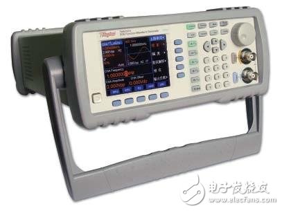
The DDS signal generator utilizes Direct Digital Synthesis technology to achieve high frequency stability and accuracy, comparable to that of a reference frequency source. This allows for fine-tuned frequency adjustment across a wide range of frequencies. The signal source can operate in modulation mode, enabling adjustments to output levels or the generation of various waveforms such as sine, square, triangle, and more.
A full cycle of a waveform is stored in a lookup table. The phase accumulator tracks the current phase of the output signal. To generate a low-frequency signal, the phase increment (Δ) between samples is very small. For example, a slow sine wave might have a Δ of just 1 degree. Each sample corresponds to a specific point on the sine wave, with 360 samples representing one full cycle. If the phase increment increases to 10 degrees, only 36 samples are needed for a single cycle. This means that the lower frequency signal will be ten times slower than the higher frequency one. By changing the phase increment, the frequency can be adjusted rapidly, allowing for complex waveform generation, including frequency sweeps and hopping signals.
DDS technology enables continuous phase transitions, making it highly flexible for applications in scientific research, communications, consumer electronics, aerospace, defense, semiconductor testing, software radio, RFID, and wireless sensing. Many companies also offer analog output products using DACs to generate analog signals. These typically use a small FIFO buffer connected to a DAC, often used for static voltages or low-frequency waveforms.
The working principle of a DDS signal generator is based on the Nyquist sampling theorem. It samples, quantizes, and encodes a sinusoidal signal from the phase Φ of a continuous signal, storing the resulting function in ROM or RAM. The phase increment is controlled by a frequency word, which determines the number of samples per cycle. As the phase increment changes, the frequency of the output signal varies accordingly. This digital signal is then converted to an analog signal through D/A conversion and filtered using a low-pass filter to remove noise and distortion.
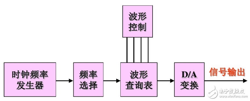
The basic block diagram of a DDS system includes four main components: the phase accumulator, which controls the frequency range and precision; the waveform memory, which stores precomputed sine wave amplitudes; the D/A converter, which generates the analog signal; and the low-pass filter, which removes unwanted noise and improves signal quality.
The reference frequency source, usually a high-stability crystal oscillator, synchronizes all parts of the system, ensuring that the synthesized signal maintains the same level of frequency stability as the oscillator. By using a fixed clock frequency to phase-sample the signal, the system can produce accurate outputs. The number of samples per unit time determines the output frequency—more samples result in a higher frequency, while fewer samples lead to a lower frequency. This is controlled by programmable frequency settings.
In terms of structure, the reference frequency clock serves as the system's operating frequency. The input frequency word is stored in either frequency register 0 or 1. After a 32-bit phase accumulation, the result is added to a phase shift register to determine the address in the internal ROM. The ROM contains a sine wave lookup table, from which the corresponding amplitude value is retrieved. This data is then converted to an analog signal via D/A conversion and further processed by a low-pass filter to refine the output.
The AD7008 is a monolithic DDS integrated circuit that includes a 32-bit phase accumulator, a sine and cosine lookup table, a 10-bit DAC, and additional features like multipliers and registers for modulation. It supports frequency, phase, and amplitude modulation, as well as digital demodulation and communication interfaces with microcontrollers.
With a 32-bit phase accumulator, the phase step (Δphase) must fall within the range of 0 ≤ Δphase ≤ 2³² - 1. The output frequency is calculated as:
$$ f_{out} = \frac{\Delta\text{phase} \times f_{clock}}{2^{32}} $$
In practice, the maximum output frequency is limited to 40% of the clock frequency to minimize phase noise and spurious signals. The Δphase value can be selected from FREQ0 or FREQ1 using the FSELECT pin. Although the phase accumulator is 32 bits, the output is only 12 bits, so full 32-bit resolution is not necessary. The 12-bit phase data is used to look up a 10-bit amplitude value. If amplitude modulation is not required, the IQ multiplier can be bypassed, and the sine wave can be directly sent to the DAC.
The full-scale output current of the DAC can be adjusted using an external resistor Rset, according to the formula:
$$ I_{out}(\text{mA}) = \frac{6233 \times V_{ref}(\text{V})}{R_{set}(\Omega)} $$
This flexibility makes DDS technology a powerful tool for a wide range of applications, providing high precision, stability, and adaptability in signal generation.