1 Introduction
The research of robot voice control system has always been one of the main contents of robot research. The traditional sound control system generally uses a PC as the core platform to control the robot. Although it has the advantages of powerful processing capability, complete voice library, and strong system update capability, the PC has a large volume, large power consumption, and high cost. Used in small and medium robots. This article takes SPCE061A as the core and designs a set of robot voice control system. Compared with the traditional PC voice control system, it has the characteristics of low cost, small size, low energy consumption and flexible and convenient use.
The robot platform used in this system is the Voyager II ground mobile robot provided by Beijing Bochuang Xingsheng Robot Technology Co., Ltd. The robot adopts a modular design concept, high load capacity DC servo control, sonar, infrared, Sensors such as vision, compass, GPS, and actuators such as manipulators. Can fully meet the design requirements of the voice control system. The overall design of the system is divided into two parts: hardware design and software design. Let us first introduce the hardware design of the system.
2 System hardware structure
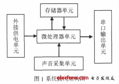
According to the situation of the robot platform, the hardware structure of the voice control system is mainly composed of four parts: a microprocessor unit, a power supply unit, a sound collection unit and a serial port output unit, as shown in Figure 1:
2.1 Microprocessor unit
This system adopts 16-bit single-chip SPCE061A of Lingyang Company as the core control chip, built-in 32K flash memory, and its high processing speed enables the chip to process complex digital signals very quickly, which is suitable for application fields such as speech recognition.
The working frequency range of SPCF061A is 0.32-49.152MHz. It has 8-channel 10-bit ADC input function and built-in microphone input function with automatic gain control. Dual-channel 10-bit DAC audio output function and A, B two I / 0 port input and output functions. It has the characteristics of high integration, reliable performance, low price and low power consumption. These characteristics fully reflect the new trend of microcontroller industrial development. At present, the application of Lingyang MCU SPCE061A is getting wider and wider, and it is very popular among users.
2.2 Sound collection unit
The transducer of the sound collection unit uses an electret microphone, and the collected sound signal is transmitted to the CPU through the MIC_IN channel through the microphone, and the MIC_IN channel is specially used to sample the voice signal. The voice signal is converted into an electrical signal by MIC, and the DC component is filtered by the capacitor, and then input into the preamplifier integrated in SPCE061A. SPCE061A's internal gain control circuit AGC can track and monitor the level of the audio signal output by the preamplifier at any time. When the input signal is too large, the amplifier gain is automatically reduced; when the input signal is reduced, the amplifier gain is automatically increased. In this way, the signal received by the A / D converter can always be kept at the optimal level, and the sound loss can be minimized, thereby improving the accuracy of speech recognition.
2.3 External power supply unit
The external power supply unit is an optional unit of the voice control system. Since the power consumption of the voice control system is very low, three 1.5V batteries can be connected externally to supply power to the system as an external power supply unit. When there is no optional external power supply unit, the battery of the Voyager II ground mobile robot can also be directly used as the power source: Lecturer Master of Engineering power supply of the voice control system, the battery power supply voltage of the Voyager II robot is 24V, and the 24V voltage is first converted to 7805 5V voltage, then use SPY0029 to convert the 5V voltage to 3.3V voltage to power SPCE061A.
2.4 Memory unit
The memory unit is also an optional unit of the voice control system. When there are few voice resources to be recognized, the FLASH memory integrated in the single-chip microcomputer can be used to meet the requirements. When the voice resources are abundant, it is necessary to connect an external memory unit to store the voice resources. In order to ensure the compatibility of the system, SPR4096 of Sunplus is selected as the external memory. LASHSPR4096 has 512K & TImes; 8bits F and 4K & TImes; 8bits SRAM. When FLASH programming or erasing, SRAM reading and writing can be performed concurrently. A bus memory interface and a serial interface, it allows the microcontroller to access the storage area of ​​FLASH SDRAM through 8_bit parallel mode or 1_bit serial mode. In this system, connect SCK and SDA of SPR4096 with IOB0 and IOB1 of SPCE061A to form serial data communication.
2.5 Serial output unit
Because the input and output levels of the SPCE061A MCU are TTL levels, and the Voyager II robot is configured with an RS-232 standard serial interface, the electrical specifications of the two are inconsistent. Therefore, to complete the serial communication between SPCE061A and the robot, the TTL level output by SPCE061A must be level-converted. In this system, MAXIM's MAX232 is used as the level-conversion chip. MAX232 uses a single power supply, only need to connect five 0.1uF capacitors, can achieve the level conversion between SPCE061A and Voyager II robot.
3 System software design
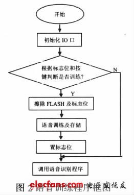
The most important part of software design is to write a speech recognition program. The speech recognition process is essentially a multi-dimensional pattern recognition process. The speech recognition program written for Lingyang MCU can be divided into three parts: training, recognition, and recognition result output.
3.1 Training procedures
When the program is run for the first time, speech recognition training is required. After the recognition training is completed, the flag bit will be set in the FLASH memory. The next time you restart, you can skip the speech training process and proceed directly to the speech recognition program. If the user needs to retrain, the flag can also be erased by pressing the key. The block diagram of this part is as follows:
Inner Battery
Inner Battery,Electric Bike Battery,Ebike Battery 36V 12Ah,Electric Bicycle Lithium Battery
Changxing Deli Technology Co., Ltd. , https://www.delipowers.com