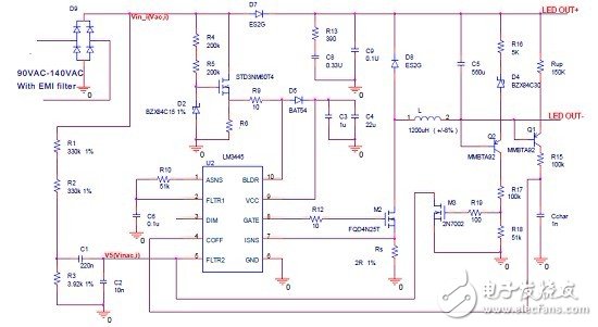
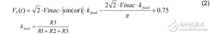
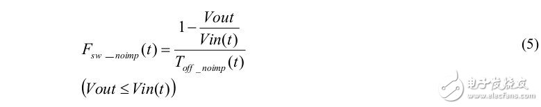
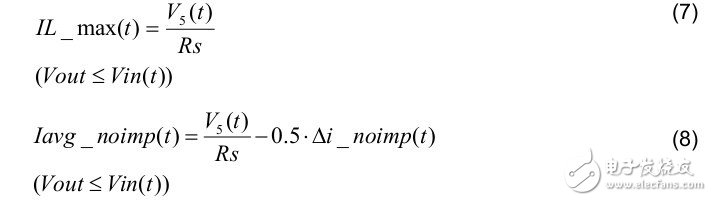
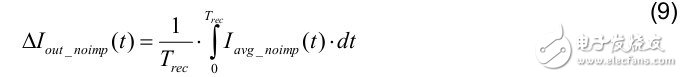
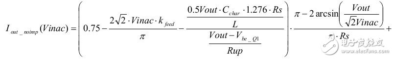
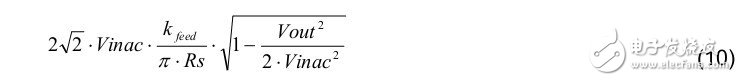
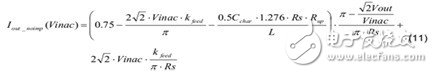
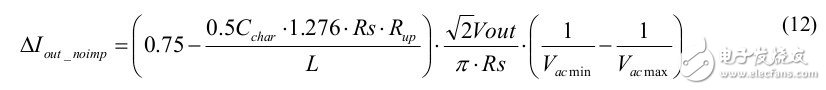
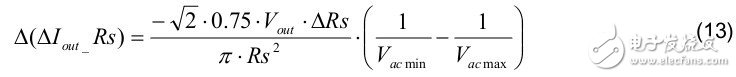
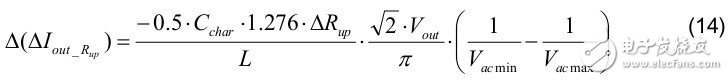
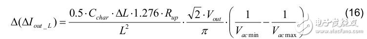
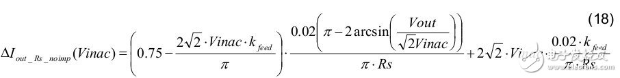
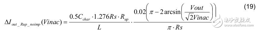
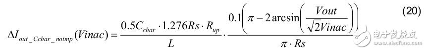
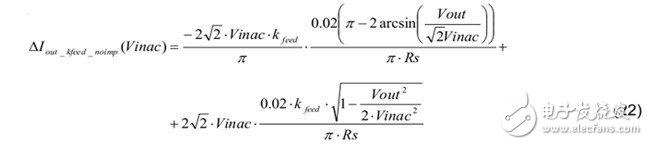
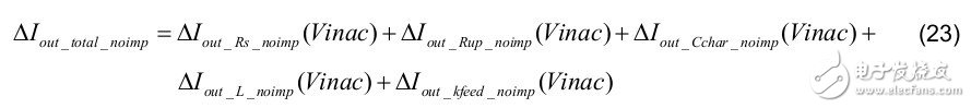
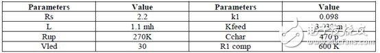
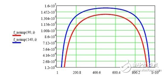
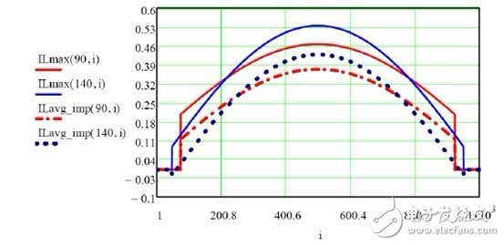
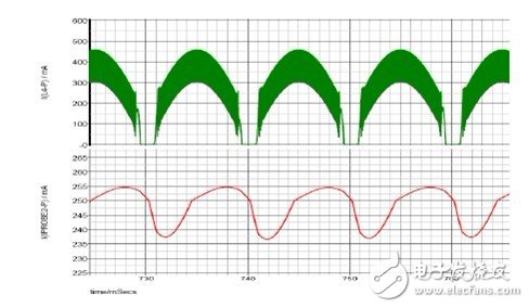
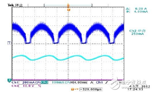
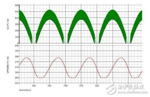
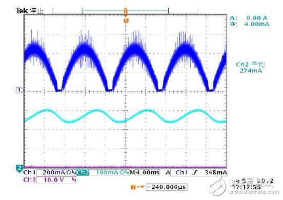
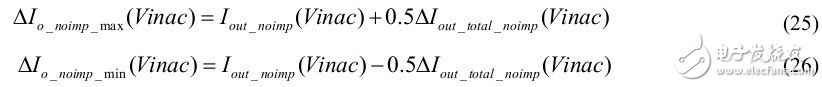
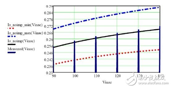
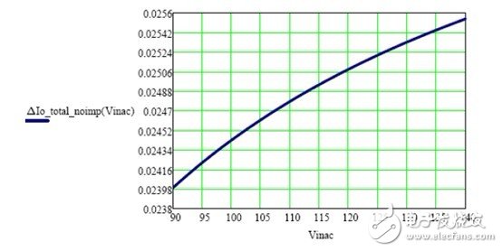
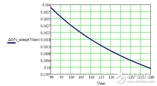
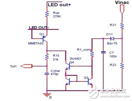
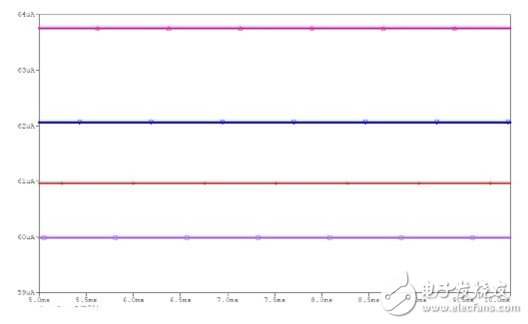
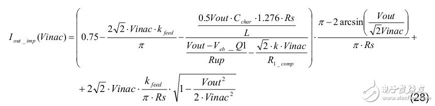
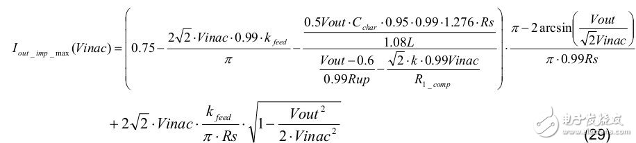
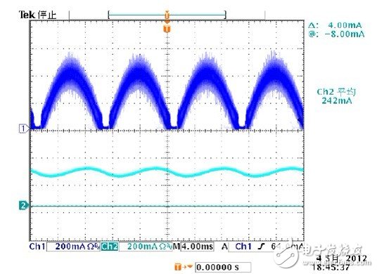
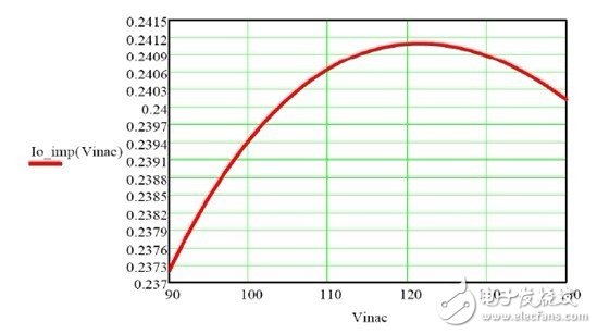
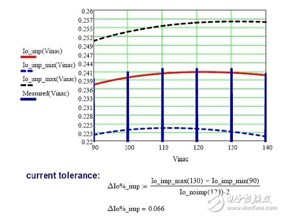
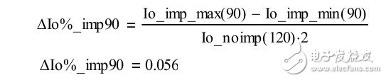
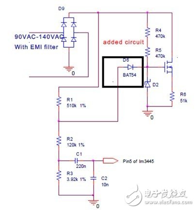
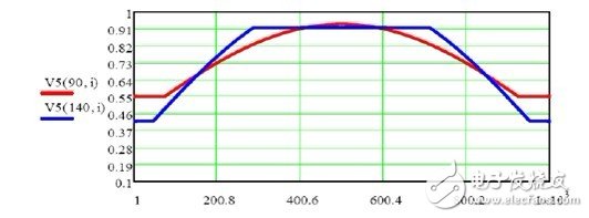
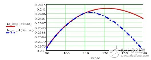
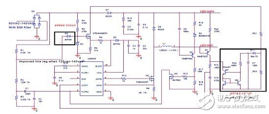
Summary This article is based on the traditional non-isolated solution of LM3445, detailing its working principle. We will derive and analyze this linear voltage regulation formula. The calculation results were verified by actual experimental results, and proved to be very closely matched. In order to evaluate the feasibility of mass production, we conducted a thorough study and analysis of the output current tolerance. The results prove that it is difficult for traditional solutions to achieve full mass production current tolerance, especially under the development trend of higher output applications required by the current market. To solve this problem, we recommend using a simple linear voltage regulator compensation circuit. We have verified this proposed solution from the theoretical calculation and experimental measurement results. According to the derived output current and linear regulation rate formula, the final total current tolerance required for actual mass production is analyzed. Based on the results obtained, we found that tremendous progress has been achieved in meeting this practical requirement. Finally, the test results and the calculation results are compared based on the prototype; it turns out that they match very well. 1 Introduction With the increasing growth of LED indoor lighting, both non-isolated and isolated solutions have become more and more popular. In particular, high linear voltage regulation, high PF and accurate constant current mode solutions have become the dominant solutions in the market. However, as the output voltage becomes higher and wider, traditional LM3444 / L3445 non-isolated applications cannot meet this margin requirement, which further limits the application of LM3445 / LM3445. In view of the above problems, the main goal of this article is high-output applications requiring precise linear voltage regulation. In this article, through some formulas in Chapter 2, the general working principle is explained. Using these formulas, we can solve the final output current. In order to evaluate the results, Chapter 3 introduces a unified formula through which the output current is simplified. In addition, Chapter 3 further details the current tolerance analysis. Chapter 4 gives some design examples based on prototypes. The article gives the calculation results and simulation results, and compares them with the experimental results. It turns out that they match very well. However, after thorough research, we found that it is still difficult to meet the current tolerance requirements for mass production. In order to solve this problem, we proposed a compensation circuit in Chapter 5. Through calculation and simulation experiments, the compensation circuit is verified. Finally, the experiment proves that the circuit significantly improves the linear voltage regulation and current tolerance performance. Using this circuit, the improved linear voltage regulator will be more competitive in practical applications, especially in LED R30 / PAR30 / A19 / E27 LED lighting applications. 2. The principle of the traditional non-isolated LM3444 / LM3445 solution Figure 1 shows a traditional non-isolated solution with higher PF. In order to facilitate the explanation of its working principle, we define the parameters as follows: • Vout: LED output voltage • I: equivalent time value within a single time period • Kfeed: the feedforward coefficient of the input AC voltage • Rs: current detection resistor • Rup: ​​toff charging resistor • Cchar: toff charging capacitor • Vinmin: the minimum value of AC input voltage • Vinmax: the maximum value of AC input voltage • Vinac: AC input voltage • _noimp: no improved linear voltage regulator circuit function • _imp: Improve the linear voltage regulator circuit function Figure 1 Traditionally proposed non-isolated solution with high PF This is a typical non-feedback loop application, but it has the following characteristics: 1. Higher PF. Through input feedforward circuit. 2. Constant current. This is achieved by the LED output voltage detection toff circuit. AC input voltage can be expressed as follows: As shown in Figure 1, C1 is greater than C2, the purpose is to achieve a higher PF value, for example: C1 / C2 = 220n / 10n. The voltage of pin 5 of LM3444 or LM3445 can be expressed as: The charging current of toff is: In the actual calculation, Veb_Q1 can choose 0.6 as the reference design. Therefore, toff can be written as: The frequency can be expressed as: The ripple current of the inductor is: Therefore, the formulas for maximum current and average inductor current can be written as: Then, the LED output current is: 3. LED current linear voltage regulation analysis based on traditional solutions Since the LED current has been derived above, we can write the total formula as: In order to derive the LED current change of each input voltage, the formula (10) can be simplified, because Vout is generally less than Vinac, and Vout is greater than Vbe_Q2. The formula can be simplified to: Then, the LED current variation over the entire input range can be derived using equation (11). We can see that the LED current change is heavily dependent on Vout, which means that when the LED voltage is lower, it can use a higher linear voltage regulator, in this case, it is very suitable for GU10 applications. 3.1 Analysis of Δ LED current change during mass production Equation (11) derives the LED current change, but this change is affected by the tolerance of Rs, L, Cchar, and Rup over the entire input range. According to the mass production requirements, we analyze it as follows: 1. During mass production, the change of Δ LED current is affected by Rs (for example: 2% tolerance) as follows: 2. During mass production, the change of ΔLED current is affected by Rup (for example: 2% tolerance) as follows: 3. During mass production, the change of Δ LED current is affected by Cchar (for example: 10% tolerance) as follows: 4. During mass production, the change of Δ LED current is affected by L (for example: 16% tolerance) as follows: 5. The extreme situation of ΔLED current change under a certain Vled during mass production is as follows: Under normal circumstances, this total change is very small compared to the LED current change. 3.2 LED current tolerance analysis during mass production In mass production, the LED current is regulated. Under normal circumstances, it is required to be within ± 5%, and its entire input range is independent of the tolerance of Vled, kfeed, L, Cchar, and Rup. From formula (9), we know that LED current changes are affected by these parameters. The following is a detailed analysis. 1. The LED current change during mass production is affected by Rs (for example: 2% tolerance) as follows: 2. The LED current change during mass production is affected by Rup (for example: 2% tolerance) as follows: 3. The LED current change during mass production is affected by Cchar (for example: 10% tolerance) as follows: 4. During mass production, the total LED current change is affected by L (for example: 16% tolerance) as follows: 5. During mass production, the total LED current change is affected by kfeed (for example: 2% tolerance) as follows: 6. The extreme LED current changes under a certain Vled during mass production are as follows: Then, according to the mass production requirements, the total LED current tolerance can be expressed as: 4 Examples of linear voltage regulation and mass production current tolerance design based on traditional solutions In order to verify the validity of the above derivation calculation results, we made a prototype according to the parameters listed in Table 1. Table 1 Prototype parameters Using the formula (5) in Chapter 2, the frequency curve shown in Figure 2 is obtained: Figure 2 The frequency of the unimproved solution less than 90Vac and 140Vac Using the formulas (7) and (8) in Chapter 2, the maximum current and average current of the inductor are obtained (see Figure 3): Figure 3 Output current of less than 90Vac and 140Vac without improvement solution Figures 4 and 5 show the simulation and experimental results of less than 90Vac and 140Vac. Figure 4 Simulation results of inductor current and output current below 90Vac Figure 5 Test results of inductor current and output current below 90Vac The measured and simulated current waveforms (see Figure 4 and Figure 5) are almost identical; the output ripple indicates that there are some small differences due to the difference between the LED simulation model and the actual test LED load. Figure 6 Simulation results of inductor current and output current below 140Vac Figure 7 Test results of inductor current and output current below 140Vac From the results shown in Figures 6 and 7, the calculation results seem to closely match the simulation results and actual measurement results. This result provides a strong theoretical support for the subsequent tolerance analysis. Use Equation 9 in Chapter 2 to calculate the standard output current; obtain the maximum and minimum output currents during mass production considering the parameter tolerance: Figure 8 Output current without improved solutions below 90Vac and 140 Vac Using the formula (23) in section 3.2, we can obtain the extreme LED current changes during mass production considering the parameter tolerance. Figure 9 The effect of component tolerance on the output current of LED without improvement solution below 90Vac to 140Vac Using the formula (24) in section 3.2, the total LED current tolerance during mass production is obtained (see Figure 10): Figure 10 The total LED current tolerance of no improved solution below 90Vac to 140Vac in mass production From formula (24), we can see that the normal LED current change from 90Vac to above 140Vac is 17mA, and the linear voltage regulation is ± 3.3%, which is acceptable for a single component. However, the main problem of the actual project is the total adjustment feasibility, that is, the total LED current tolerance under the consideration of component tolerance. From Figure 8, we know that the output current change affected by the component tolerance is about 32mA. Therefore, the total LED current tolerance during mass production is more than ± 8%, as shown in Figure 10. In the actual production process, this is also difficult to achieve. From the above analysis, we can know that linear voltage regulation is the key to improve the total tolerance of the input range. 5 Working principle of the improved non-isolated LM3444 / LM3445 solution In order to improve linear voltage regulation, we recommend using the line voltage compensation shown in Figure 11. Figure 11 Improved line voltage compensation circuit In order to reduce the latching current tolerance of the circuit shown in FIG. 11, higher precision resistors R21, R23, and R1_comp can be used. In order to reduce the impact of the forward voltage of D11, Q3 and Q4, we recommend that the voltage of C7 is slightly higher (for example: 20Vdc). In order to know the current tolerance at different temperatures, V_C7 is set to 20V, Q4's V_c is 20V, and R_comp is 300K, and then SPICE temperature scan simulation is performed. The results are shown in Figure 12. Figure 12 Simulation results of temperature scan below 0 ° C, 25 ° C, 50 ° C and 85 ° C From this result, we know that the temperature tolerance is ± 3%, so we can enter the actual design. After installing the compensation circuit (see Figure 11), the charging current of the improved toff is: In order to reduce the influence of Vbe of Q3 and Q4 (as shown in Figure 11), we recommend that the coefficient k of equation (27) be as large as possible, so that we can ignore Vbe in the design. The formulas for maximum current and average inductor current are the same as formula (7) and formula (8) in Chapter 2. The final LED current formula is as follows: If the tolerances of other components are not considered, the standardized formula for the output LED current can be written as: In the actual calculation process, we can make the following provisions: 0.95Char, 0.99Rs, 0.99Rup, 1.08L and 0.99 kfeed in order to get the maximum LED output current. The calculation formula is as follows: Using the same analysis, we can make the following provisions: 1.05 Char, 1.01Rs, 1.01 Rup, 0.92 L, and 1.01 kfeed in order to obtain the minimum LED output current. The calculation formula is as follows: Then, we can get the following calculation method of frequency range and inductor current waveform. Figure 13 Frequency below 90Vac and 140Vac Figure 14 Inductor current below 90Vac and 140Vac Figure 15 and Figure 16 show the experimental results below 90Vac and 140Vac Figure 15 Test results of inductor current and output current below 90Vac Figure 16 Test results of inductor current and output current below 140Vac Figure 17 shows the results of the linear regulator calculation: Figure 17 Linear regulator calculation improved to less than ± 1% The output current is a nonlinear curve of the input voltage, and the nonlinear curve. The compensation parameters greatly affect this curve. In actual design, engineers can optimize this curve by adjusting the line pressure compensation parameters. In order to verify this result, the measurement result shown in FIG. 18 is used to compare with the calculation result. Figure 18 Extreme current tolerance calculation improved to ± 6.6% From Figure 18, we can know that due to the use of the improved linear regulator circuit, the extreme current tolerance has also been improved. In order to achieve this very severe extreme current tolerance, our solution must be further improved to meet the requirements of some special users. If you consider the current tolerance below 90Vac, you can get: This goal can be achieved if the tolerances above 90Vac are basically the same; therefore, Figure 19 shows an alternative recommended method. Figure 19 Linear voltage regulation improvement circuit below 120Vac to 140Vac The calculation method of pin 5 voltage of LM3445 / LM3444 is shown in Figure 20 and Figure 21: Figure 20 LM3445 / LM3444 pin 5 voltage when the circuit of Figure 20 is added Figure 21 Linear regulation is greatly improved after using the circuit in Figure 19 Through the previous analysis, we can conclude that this circuit can help improve linear regulation. However, if the current tolerance of the line voltage compensation circuit can meet the requirements of mass production, this additional diode circuit cannot be used. However, if there is extra space in the PCB layout, TI still recommends using this additional diode circuit in the actual design. Finally, Figure 22 shows the complete improved solution for the alternative method. Figure 22 The complete solution of the alternative method for greatly improving the linear voltage regulation in conclusion Based on the traditional non-isolated LM3444 / LM3445, this article thoroughly analyzes the linear regulation and current tolerance of the output current. As a result, linear regulation is not ideal. In order to solve this problem, we propose an improved solution. In addition, we also explained the linear voltage regulation and total current tolerance. We have proved the feasibility of this solution through theoretical analysis and practical experiments.
Ceramic wall heaters get the name from the constructions of the PTC heating element, which is made of ceramic and Aluminum that conducts heat very good. Electric Ceramic Heater with Over Heat Protection, 2 Heat Settings, Quick Heat up for Home and Offices.
Wall-mounted Ceramic heater use a much smaller PTC heating unit, and a surface area for the device that can be relatively tiny and thing, yet wide.
We have Ptc Wall Heater with Erp program.
Welcome to OEM
thanks
Ptc Wall Mounted Heater,Ptc Wall Heater,Room Heater Fan,Heating And Cooling Fan Fenry manufacturing Co., Ltd , https://www.cnfenry.com