16L Agriculture Drone,Farm Fumigation Drone,Agricultural Sprayer Uav,Agriculture Drone Xuzhou Jitian Intelligent Equipment Co. Ltd , https://www.jitianintelligent.com
**1. The Meaning of Antenna Decoupling Network**
In most wireless systems, antenna units are placed as far apart as possible to minimize the mutual coupling effect between them. However, in compact devices like smartphones, the limited space often results in closely spaced antennas, which leads to strong electromagnetic coupling. Research has shown that when the distance between two antennas is less than or equal to half the wavelength of the signal, the received signals are significantly affected by this coupling. As the spacing continues to decrease, the impact on the system's performance becomes more severe. Therefore, in such confined spaces, it's crucial to address mutual coupling during the antenna design phase.
In engineering, isolation is commonly used to quantify the level of mutual coupling. For WiFi band antennas, the required isolation is typically above 15 dB. Several techniques can be used to reduce coupling, including adjusting antenna spacing and polarization, designing decoupling networks, introducing defective structures, or using current neutralization lines. These methods can be analyzed using simulation tools like HFSS. Decoupling network technology is particularly effective in reducing coupling between antennas. The design of the antenna unit and the decoupling network can be done separately, which simplifies the overall design process. In this article, we will explore how to design an antenna decoupling network using HFSS simulation.
**2. Steps for Designing an Antenna Decoupling Network Using HFSS Simulation**
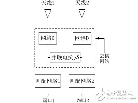
From a network analysis perspective, the goal of decoupling is to make the mutual impedance of a multi-port network approach zero, or to reduce the inverse transmission coefficient of the scattering matrix to near zero. A common structure for a decoupling network is illustrated below. The principle involves analyzing the network parameters step by step. In simple terms, the process can be broken down into three main steps:
First, due to good initial impedance matching between the antennas, there is strong coupling. The purpose of the decoupling network (D) is to transform the complex transmission admittance between the two ports into a purely imaginary value.
Second, a parallel reactance is introduced to cancel out the previously created imaginary admittance, resulting in a zero transmission admittance, thus achieving decoupling.
Third, the introduction of the decoupling network may cause impedance mismatch at the antenna port. To resolve this, a matching network is added to restore proper impedance matching.
HFSS not only provides accurate simulations of the far-field radiation patterns of antennas but also supports efficient electromagnetic analysis of decoupling and matching networks. Let’s take a practical example:
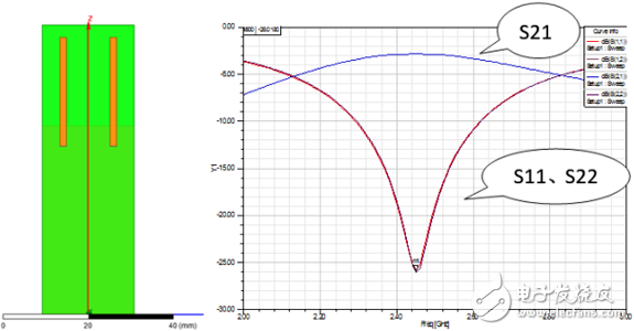
1. Two closely spaced WiFi band monopole antennas (operating at 2.4–2.5 GHz) show poor isolation, with only 3 dB at the center frequency.
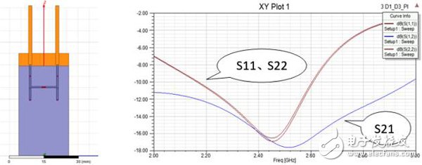
2. By implementing a lumped RLC boundary condition for the decoupling network D and re-simulating, the isolation improves significantly, although the antenna resonance point shifts slightly.
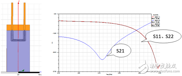
3. Finally, a matching network is designed and simulated, resulting in both acceptable isolation and VSWR values.