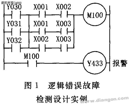
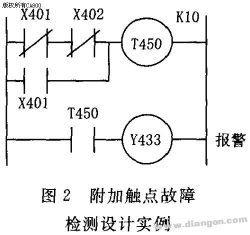
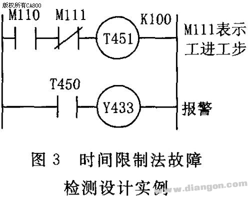
1. Fault Diagnosis Design for Switching Signals When a PLC controls electromechanical devices, the switch signals from components like switches, buttons, and relay contacts are connected to the PLC's input ports. Each of these inputs corresponds to a specific memory address in the PLC. The system reads the current state of these input bits to identify potential faults. Essentially, the diagnostic process involves comparing the expected (normal) state of an input bit with its actual state. If they match, the device is operating correctly; if not, it indicates a fault in the corresponding component. Several common diagnostic techniques are used to detect such issues. These include logic error detection, additional contact monitoring, and time-based checks. 1.1 Logic Error Fault Detection Method In normal operation, there should be a logical relationship between the input and output signals of the control system and the internal relay signals. If a component fails, this logical relationship can break, causing the system to malfunction. By establishing the expected logical relationships under fault conditions, the system can trigger alarms or take corrective actions, such as stopping the feed or spindle rotation, when a discrepancy is detected. The logic program for checking the status of three travel switches—X001 (start point), X002 (fast forward end), and X003 (work end)—is shown when the machine tool's slide table is in motion. Y030, Y031, and Y032 represent fast forward, work forward, and fast reverse. In any operational state, only one of the three switches should be active at a time. If two or more are activated simultaneously, it suggests a faulty switch, and the system should halt for inspection. 1.2 Additional Contact Connection Diagnostic Method During PLC retrofitting, only the most essential external input contacts are typically used to save input points. However, to improve reliability, important components may have both normally open and normally closed contacts connected to separate PLC input ports. Software routines then monitor these contacts to detect faults such as stuck relays or failed components. For example, if a relay K exists in the electrical system, its normally open contact could be connected to X401, while its normally closed contact is connected to X402. When the relay coil is energized, the normally closed contact opens, and the normally open contact closes. If this does not happen, a fault is detected. This method helps ensure accurate fault identification, especially when input ports are available for redundancy. 1.3 Time Limit Method In automated machine tools, each action must be completed within a defined time frame. If an action exceeds the allowed time, it may indicate a fault. To detect this, a timer is started when a step begins. The timing should be longer than the normal operation cycle. If the timer triggers, it signals a fault, and the system can respond accordingly, such as by stopping the process or initiating a shutdown. Figure 3 illustrates the fault detection process during the transition from fast forward to work mode. M110 represents the fast forward step. Once the stroke switch is triggered, the system should move into the work mode. If this transition takes longer than expected, it is considered a fault in the fast forward phase, possibly due to a faulty switch, hydraulic issue, or electrical problem. While the exact cause may not be identified, the system can prevent further damage by halting operations. 2. Fault Diagnosis Design for Analog Signals Since PLCs support analog processing, they can monitor critical parameters such as pressure, flow, temperature, and vibration in machine tools. Sensors and transmitters are used to collect these data, which are then processed by the PLC’s A/D module. Real-time comparison with set thresholds allows the system to determine whether the machine is operating correctly. If abnormal values are detected, the system can alert the operator or initiate a shutdown. Figure 4 shows the block diagram of the parameter monitoring system, highlighting how real-time data is collected, analyzed, and acted upon to maintain safe and efficient machine operation.
Fastener is a kind of mechanical parts used for fastening connection and widely used.A wide variety fasteners of Screw Bolt nut can be found on all kinds of achinery,equipment,vehicles,ships,railways,bridges,building,structures,tools,instruments,meters and supplies.It is characterized by a variety of specifications,performance and use of different and standardization,serialization,generalization of the species is also very high.Therefore,some people have national standard fasteners called standard fasteners or referred to as standard parts.
Hardware Fastener,Stainless Steel Fastener,Screw Fastener,Female Fastener,China Fastener BAODING JIMAOTONG IMPORT AND EXPORT CO., LTD , https://www.chinagroundscrew.com