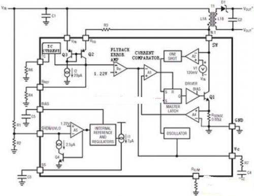
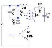
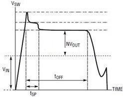
introduction Since the advent of single-chip switching power supplies in 1994, it has created conditions for the promotion and popularization of switching power supplies. The application of switching power supplies involves various fields of electronic and electrical equipment, such as program-controlled switches, communications, electronic testing equipment power supplies, control equipment power supplies, etc., which have widely used switching power supplies, which has further promoted the rapid development of switching power supply technology. Various new technologies, new processes and new devices have sprung up, and the application of switching power supplies has become increasingly popular. The high frequency of switching power supplies is the direction of its development. From the initial 20 kHz to the current hundreds of kHz or even a few megahertz, high frequency brings the miniaturization of switching power supplies. At present, switching power supplies are developing in the direction of high efficiency, energy saving, safety and environmental protection, miniaturization and light weight. Introduction to LT3573 The LT3573 is a monolithic switching regulator designed for isolated counter-attack topologies. In the isolated flyback topology, the primary circuit of the transformer needs to constantly sense the change of the output voltage of the secondary side in order to maintain the output voltage stable. In the past circuit topology, optocoupler devices or additional transformer windings are often used to obtain output voltage feedback information. The problems with the optocoupler device are: 1 consumption of output power; 2 cost increase, the circuit structure is complicated; 3 limited dynamic response, device nonlinearity, aging, etc., will cause trouble. In addition, if a transformer or transformer winding is added, the physical size of the transformer will increase, the cost will increase, and the dynamic response will not be good. The LT3573 does not require an external optocoupler or a third winding. Its unique built-in flyback error amplifier, when the secondary winding current is zero, the flyback error amplifier starts sampling the output voltage information directly from the transformer's primary side. The voltage waveform detects the change of the output voltage and automatically maintains the stability of the output voltage. This is also the highlight of this IC design. The flyback voltage is converted into a current due to the action of RFB and Q2. This current flows almost all through the resistor RREF, forming a feedback voltage, entering the flyback error amplifier, and comparing it with a reference voltage of 1.22V, so that the subsequent circuit can adjust the switch tube. The duty cycle is achieved for the purpose of stabilizing the output voltage, as shown in Figure 1. Figure 1 LT3573 internal topology block diagram A 1.25A, 60V NPN power switch and all control logic are integrated into the LT3573 in a 16-lead MSOP package. It greatly simplifies the peripheral circuit design of the integrated block application. It works in the input voltage range of 3V~40V, and the maximum output power can reach 7W. It can be applied to many fields that require isolated power supply, such as industrial, medical, and data. Communications, automotive applications, low-power PoE and VoIP phone interfaces. The LT3573 operates in boundary mode, which allows the use of smaller transformers compared to a peer-to-peer continuous conduction mode design. Clamp circuit design The transformer leakage inductance Lsl (whether primary or secondary), as shown in Figure 2, will cause a voltage spike to appear on the primary side. When the output switch is turned off, this spike becomes sharper as the higher load current, which requires the energy absorbing network to consume the energy stored in the leakage inductance. In most cases, a snubber circuit is required to avoid overvoltage breakdown of the output switch node. Therefore, the transformer leakage inductance is minimized. Select the absorbing network clamp flyback switch voltage spike. Due to the voltage spike generated by the leakage inductance of the switching transformer, the flyback voltage can be calculated by: (1 Where: VF - transformer secondary side rectifier diode D2 forward voltage drop; ISEC—the secondary current of the transformer; ESR—the total impedance of the secondary circuit; NPS—the effective primary and secondary side turns ratio of the transformer; VOUT—output voltage. The sum of this voltage and the input voltage (VIN + VFLBK) is directly added to the collector of the power switch tube Q1, which is liable to cause secondary breakdown of the power switch tube Q1 and damage. In order to clamp the voltage spike to within the rated value of the switch, the RCD absorbing circuit is most commonly used, so that during the turn-off of the switch, the energy stored in the leakage inductance is transferred to the absorbing network capacitor C1 and finally consumed on the resistor R1. as shown in picture 2. Figure 2 RCD absorption circuit diagram Here, the switching diode D1 has a switching speed fast enough. Otherwise, when the switching transistor is turned off, the leakage inductance peak cannot be transmitted to the capacitor C1 in time, and an instantaneous high voltage is generated at the collector of the switching transistor Q1, as shown in FIG. Therefore, Schottky diodes are usually the best choice. Fig. 3 Schematic diagram of collector voltage waveform of switch tube Q1 Once the clamp diode D1 is turned on, the leakage current will be absorbed by C1, and the absorption time must not be longer than 150ns. The design of the tSP switching transformer shown in Figure 3 This high output Football Stadium Lights have a lumen count of 160,000 and a beam angle of 60 degrees. The high output 5000K Tennis Court Lighting is ideal for lighting up big stadiums and sport facilities such as basketball courts, tennis courts and soccer fields, or other large areas.Football Field Lights are built with patented technology to last for 45,000+ hours, eliminating the need to frequently replace your fixture. By replacing HIP/HID/MH bulbs/fixtures with 200W LED you are reducing your electricity cost by up to 80%.This large area Led Sports Field Lighting has an Ingress Protection rating of 67, meaning dust tight and protected against water immersion. The durable composition of this outdoor led fixture along with the IP67 rating ensures your fixture won`t give in to the elements.It has 5-year unlimited warranty. Football Stadium Lights Football Stadium Lights,Tennis Court Lighting ,Football Field Lights,Led Sports Field Lighting Shenzhen Bbier Lighting Co., Ltd , https://www.chinabbier.com