In recent years, the electronic components of automobiles have been continuously improved, helping to improve fuel economy, reduce emissions, and enhance safety, lighting, in-vehicle networks and infotainment systems. Among them, car headlights are an important part of safe driving. ON Semiconductor's innovative and leading industry automotive adaptive headlamp system (AdapTIve Front-lighTIng System, AFS) motor drive solution overcomes the limitations of traditional headlamps and helps Improve driving safety. This article analyzes the characteristics of AFS, introduces the AFS solution of ON Semiconductor, and the application design points to help customers apply the automotive AFS solution.
Application Advantages and Working Principles of Adaptive Headlamp System (AFS)
The light of the traditional car headlights is always consistent with the direction of the car body. When the car turns, it cannot effectively illuminate the blind spot inside the curve. If there is a person or object inside the curve, and the speed is not properly lowered, it will bring safety hazards. As shown in Figure 1. In comparison, the AFS function provides a swiveling adjustment that rotates at the angle of the steering wheel to project an effective beam onto the front surface that the driver needs to see to help reduce safety hazards.
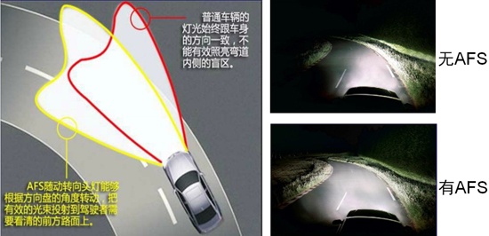
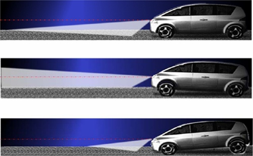
Figure 1: The rotation adjustment (left) and horizontal adjustment (right) of the AFS function.
In addition to dynamic rotary adjustment, the AFS function provides dynamic level adjustment. This function adjusts the headlight level according to the signal of the load axis sensor, which can adapt to different loads and different slope environments. As shown in the right side of Figure 1, the above picture shows the effect of the AFS function on the light level under normal conditions. The middle picture shows the effect of the light up under the bumpy conditions of the car when starting or going uphill. The picture below is under braking or downhill conditions. The lighting level sinks the lighting effect. It can be seen that AFS can dynamically adjust the light height according to the horizontal tilt of the vehicle body to improve the lighting effect and enhance safety. The structure diagram of AFS working principle is shown in Figure 2 and Figure 3, respectively.
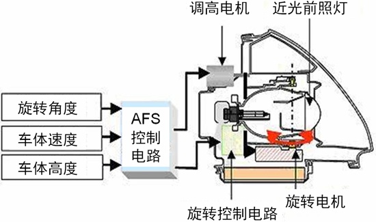
Figure 2: Structure diagram of the working principle of AFS.
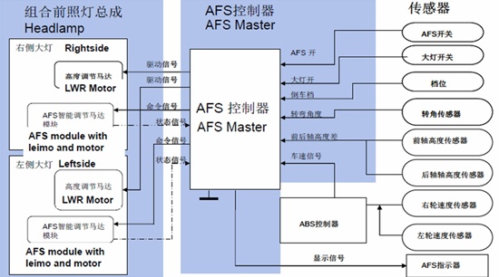
Figure 3: Structure diagram of the working principle of AFS (continued).
Stepper motor driver placement position selection
The rotation and level adjustment of the AFS of the car is realized by using a stepping motor. The motor reacts according to the feedback data of many sensors around the vehicle. Therefore, the designer needs to adopt a suitable stepping motor driving scheme and put it in the suitable s position.
There are two options for the position of the stepper motor driver that controls the AFS function. One method is called direct drive, and typical products such as NCV70522. In this scheme, the stepper motor driver chip is mounted on the same printed circuit board (PCB) as the main microcontroller (MCU). This board is far from the headlamp components and associated stepper motors, and each motor needs to be connected to a corresponding signal.
Another method is mechatronics, a typical product such as AMIS-30623. In this method, the stepper motor drive IC can be directly mounted in the stepper motor structure, and only the shared ground wire is connected to the LIN bus signal. This method is extremely beneficial because the interface between the MCU and the mechatronics module requires only a low electromagnetic compatibility bus. The mechatronics method adopts a modular design, and the headlamp assembly is easy to maintain and maintain, and the benefits are obvious. The structure of the two methods is shown in Figure 4.
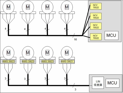
Figure 4: Two different stepper motor driver placement methods.
ON Semiconductor's main AFS stepper motor driver products and key features
ON Semiconductor offers a wide range of stepper motor driver products such as AMIS-30621, AMIS-30623, NCV70627, NCV70521 and NCV70522. Among these products, AMIS-30621, AMIS-30623 and NCV70627 use LIN communication, while NCV70521 and NCV70522 use SPI communication. Among them, AMIS-30623 is a single-chip micro-stepping motor driver. It is a dedicated mechatronics solution for remote connection to the host via LIN. The chip receives positioning commands via the bus and then drives the motor coils to the desired position, configurating parameters such as current, speed, acceleration and deceleration. The chip comes with motor stall detection.
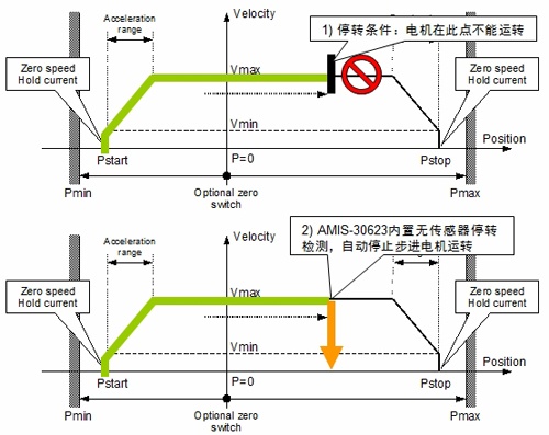
Figure 5: Schematic diagram of the working principle of AMIS-30623.
The NCV70522 is an SPI communication stepper motor driver IC with a regulator and watchdog function. This single-chip microstepping motor driver features output current selectivity, SPI interface, embedded 5V regulator, and watchdog reset. The chip receives the "next microstep" command through an input pin pulse signal, and outputs parameters such as coil current and microstep number. The integrated SPI bus allows parameter setting and diagnostic feedback. A typical application circuit diagram of the NCV70522 is shown in Figure 6.
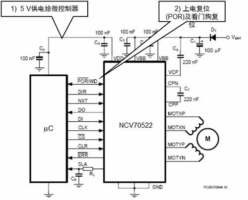
Figure 6: Typical application circuit diagram of NCV70522.
NCV70522 application design points
We take NCV70522 as an example to introduce the design points of this chip in AFS application. Control elements of the NCV70522 include stride mode, NXT input, and motor run direction (DIR) control.
1) SLA signal characteristics
The NCV70522 includes speed and load angle (SLA) outputs to create a stall detection algorithm and control loop to adjust torque and speed based on the motor's back electromotive force (BEMF).
2) SPI register
The NCV70522 uses standard 4-wire SPI communication (CLK, CSB, DI, DO) and contains three 8-bit Control (0, 1, 2) and four 8-bit Status registers (0, 1, 2). , 3).
3) Reset
When the CLR pin is low (0), the device is in normal mode; when the CLR pin is high (1), the device is reset. Reset Number The device internal register value is cleared to the initialization value.
4) Set the coil output current
The NCV70522 offers a variety of output current modes that can be selected via the SPI setting of the CUR[4:0] registers. The changed current will be updated in the next Pulse Width Modulation (PWM) cycle.
5) Stride setting
The NCV70522 offers a choice of seven modes from full-step to 32-microstep, which can be set via the SPI register SM[2:0].
6) NXT control
The NXT signal is used to control the step position of the motor, and proceeds to the next step according to the Ix and Iy information corresponding to the ammeter. Even if the motor is not running, the step position is changed as it is, but Ix, Iy does not output.
7) Stall detection
Stepper motors can sometimes stall during AFS applications. Once the motor is stalled, the electronic control unit (ECU) will lose track of the headlamp position and react inappropriately, creating a very serious safety problem, so stall detection is essential in AFS applications.
The NCV70522 microstepping stepper motor driver provides BEMF output through the SLA pin, which means it can perform stall detection calculations in real time and adjust the detection level according to different conditions. In particular, this BEMF voltage is sampled during each so-called "coil current zero crossing". Each coil has two zero current positions in each electrical cycle, so there are four zero-crossing observation points per electrical cycle, so four BEMFs can be measured. If two of the four "coil current overcurrent points" have a SLA level below 1.5 V, they are in a stalled state. We need more than 2 consecutive electrical cycles to be considered as stalling to be truly blocked.
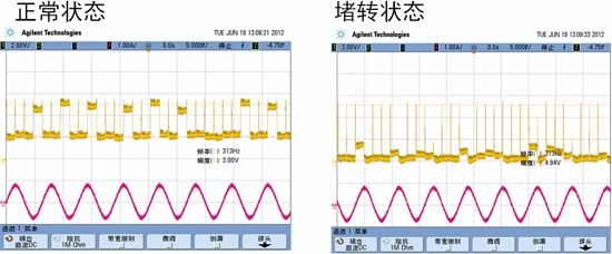
Figure 7: The stall detection function of the NCV70522.
to sum up:
The adaptive front lighting system (AFS) is more and more widely used in smart car electronic products. By driving the stepping motor to control the lighting angle adjustment in real time, it can effectively increase the safety of driving. ON Semiconductor has developed a series of driver chips for stepper motors in the AFS system to enhance the safety of the car for the customer's design. This paper introduces the AFS characteristics, driver IC and program design points, especially the difficulty of stepping motor drive--blocking detection, helping customers to develop effective AFS solutions quickly and accurately.
Reference materials:
1, NCV70522 data sheet
2, "Anson Semiconductor's solutions and design points in AFS applications" webinar
Innovative far infrared heat pad, the most efficient and reliable tools for providing suitable temperature for your pets.
1. The heat transfer rate is up to more than 90%, saving energy and
electricity
2. The honeycomb circuit has planar heating, and the effective
heating area accounts for a large proportion, about 90% of the
product area, and the heated object is heated more evenly
3. Radiate far-infrared light wave, making the heat source softer
4. Wide circuit and connected design, no need to worry about
crimping the circuit break
5. Add the thermostat protection device, which can ensure the
product safety under bad conditions and effectively prevent the
superhigh temperature of the object being heated
XHC-F034D
Ipower Controller Pad,Heat Mat And Thermostat Reptiles,Amphibians Heat Pad
ShenZhen XingHongChang Electric CO., LTD. , https://www.xhc-heater.com