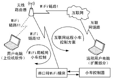
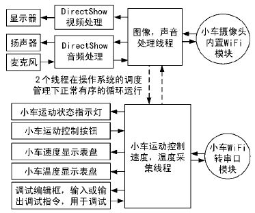
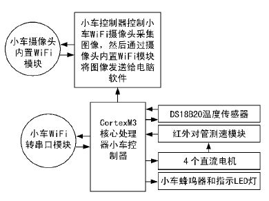
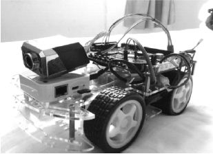
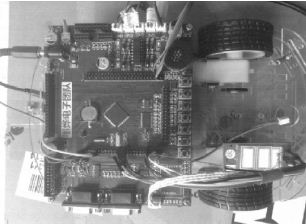
The WiFi Internet of Things trolley design adopts the computer host computer software to control the movement of the trolley through wireless WiFi and collect the information of the trolley. Compared with the traditional "smart car", the main feature is the use of 32-bit high-performance microcontroller control, Internet communication mechanism and computer PC software control. This solution combines computer software, network communication, image processing, graphic display, motion control, speed acquisition and temperature acquisition, and has the relevant characteristics of “Internet of Thingsâ€. Most of the traditional car control uses infrared communication, and the remote control is used for control, which is not only limited by distance, but also far from the intuitive and beautiful computer software. Internet communication enables the car to have remote control capabilities, which is beyond the reach of infrared communication. In addition, the car control chip of this solution adopts Cortex-M3 single-chip microcomputer, which has a very rich peripherals, which lays a foundation for the function upgrade and expansion of the car in the future. 1 overall design The purpose of the WiFi IoT car design solution is to use computer software (referred to as the upper computer) to communicate with the car control terminal (referred to as the lower computer) through the Internet, thereby controlling the movement of the car, collecting the speed, temperature and video monitoring functions of the car. . The overall design is shown in Figure 1. There are 2 communication modes available in the figure. Among them, “WiFi LAN car control†adopts the way of LAN, and the upper computer, wireless router and car form a local area network to realize the purpose of controlling the car by the upper computer. "Internet remote car control program" is a remote Internet method, which combines the upper computer and the small car to form an Internet, thereby realizing the purpose of remotely controlling the car. The technology of the two schemes is similar. Due to the limitation of experimental conditions, this design uses the local area network trolley control as an example to explain. Figure 1 overall design From the communication point of view, the wireless router is the data center of the upper computer and the lower computer. The upper computer creates a network interface to connect with the router through Winsocket socket programming, and the car end passes the WiFi module through a serial port to pass the serial port data through the WiFi. The module converts to a WiFi signal to interact with the router. In this process, both the upper computer and the lower computer WiFi module have a separate LAN IP address. Network communication can be achieved by using the IP address of the upper computer and the lower computer. From the perspective of control, the upper computer is the control center of the trolley. The upper computer sends a command to the trolley through the “buttonâ€. After receiving the command, the trolley returns the relevant data to the upper computer. The upper computer receives the data returned by the trolley. Parse and display it. 1.1 PC software design The main function of the upper computer is to control the movement of the car, display the speed of the car, the surrounding temperature and the camera captured by the car. As shown in Figure 2, these functions are completed by two threads: "image, sound processing thread" and "car motion control, speed, temperature acquisition thread". The previous thread is mainly responsible for receiving and processing the image information and audio information transmitted by the WiFi camera with the car. This part mainly involves the related technology of DirectShow. The latter thread is mainly responsible for the control of the car movement, including "forward, backward, left turn, right turn, stop, acceleration, deceleration, turn signals and horns" and receiving temperature and speed information for handling the car's return, and displaying it with a virtual chart. come out. The 2 threads of the host computer software have created an irrelevant socket. The former is used for data interaction with the car WiFi camera, and the latter is used for data interaction with the car serial port to the WiFi module. Figure 2 PC software design 1.2 lower computer software design The lower computer software design, that is, the programming of the Cortex-M3 core processor, is shown in Figure 3. The design scheme mainly includes: camera control, control of 4 motors of the car, collection of temperature data of DS18B20, data collection of infrared tube speed module, processing and packaging of data after data acquisition. The camera control, motor control, and temperature and speed acquisition are all obtained in the form of functions. When the lower computer receives the relevant command from the host computer, it calls the corresponding function to obtain the result and then sends it to the host computer in a fixed format. Figure 3 lower computer software solution The core of the communication between the lower computer and the wireless router is the serial to WiFi module. Through this module, the serial data sent by the lower computer can be directly converted into a WiFi signal and transmitted. It can be configured in a variety of ways before using this module, and as long as it is configured, it can communicate with the established WiFi access point. 2 Design plan features and extension instructions 2.1 Features This program is based on the concept of combining computer software, Internet communication and single-chip technology. From the selection of the single-chip microcomputer, the determination of the communication scheme and the design of the PC software, it has great special features with the traditional "smart car". The following are the three major features of this design: 1 The control chip of the car adopts the powerful Cortex-M332 high-performance, low-power processor. The chip has a wealth of peripherals. The chip also supports the RLTx real-time operating system provided by ARM, which is very convenient to use. 2 Communication method adopts TCP / IP communication protocol, and uses wireless WiFi technology to realize control of the car. This communication scheme (Figure 1) can connect to a remote network with a private IP address, and can remotely control the car through a remote network, which will have good value in the fields of "smart home" and "remote medical care"; 3 Using computer host computer management software, MCU control, network communication and computer software are effectively combined. This solution is designed to manage the car with the PC software, which is in line with the design concept of simplifying and integrating complex control. 2.2 Extended Description The powerful and rich peripheral resources of the Cortex-M3 microcontroller provide a strong foundation for the expansion of the design. In addition to the functions that have been implemented, the MCU has 2 ports left unused, which allows the car to add the following functions: GPS navigation, voice and GSM/GPRS texting, calling and wireless Internet access. 3 Program difficulties and key technologies The difficulty of the program is: 1 The movement of the upper computer controls the car to have high requirements for real-time performance, and the speed of collecting the car is displayed by the dial, which puts forward the requirement for the stability of communication, and for the TCP/IP communication with inherent delay It is even more difficult; 2 Image processing is mainly based on the technology provided in the online DirectShow development guide. Many internal processing mechanisms and signal filters are difficult to use; 3 The speed dial of the upper computer shows that the speed is inconsistent, and occasionally there is a phenomenon of “deadâ€. The key technologies are: 1 the development of the communication protocol; 2 the method of the lower computer to collect and process the information; 3 the upper computer socket programming, the speed dial dynamic display speed; 4 the upper computer display the trolley monitoring video screen; 5 the car as the WiFi access point Into the network. 4 System simulation results analysis 4.1 WiFi Internet of Things trolley overall appearance The overall appearance of the car is shown in Figure 4 and Figure 5. The system consists of the upper computer and the small car, and the trolley control circuit is placed on the trolley. The car controller mainly includes: motor control, speed measurement, temperature measurement, communication, image acquisition and wireless routing. Figure 4 WiFi Internet of Things trolley Figure 5 car top view 4.2 System overall debugging WiFi IOT trolley control system PC interface mainly includes: network settings, function settings, video monitor area, motion control area, speed display area, temperature display area and debugging window. The network setting is used for network connection between the host computer and the trolley. Enter the IP address of the trolley and click “Connectâ€. The video surveillance function requires the WiFi camera to be installed on the car. You can connect to the IP address of the WiFi camera by clicking the “Call†button below the video display box. If the connection is successful, you can obtain the image captured by the camera. The motion control area is used to control the movement of the trolley and display the turn signals, horns, etc. of the trolley. The speed display area is a speed dial used to display the real-time speed of the car. The temperature display area is a graphical interface of the thermometer that displays the temperature of the DS18B20 sensor on the cart. The communication debug window is used when debugging the program. 4.2.1 Network connection Network connection debugging uses the TCP network debugging assistant downloaded from the Internet. First, set the TCP debugging assistant to the server mode, set the server monitoring IP to 192.168.16.110, and set the port to 345 to connect to the network. This IP address and port number are UART to WiFi module. The IP address and port number are set by the MCU with the AT command. After the network connection is successful, the car will continue to send "014, SR1, TE1, 029.6", indicating that the current temperature of the car end is 29.6 °C. 4.2.2 Car movement The debugging of the trolley motion control part is also debugged by the host computer and the TCP network debugging assistant. After connecting the network, click “↑â€, “↓â€, “â†â€, “→â€, “█â€, “Acceleration†and “Deceleration†on the host computer. ":014, SG1, UP1,;", ":014, SG1, DO1,;", ":014, SG1, LE1,;", ": 014, SG1, RI1," are sequentially received on the debug assistant receiving window. ;", ": 014, SG1, ST1,;", ": 014, SG1, AD1,;" and ": 014, SG1, SU1,;", respectively, "forward", "backward", "left turn" , "Right turn", "Stop", "Acceleration" and "Deceleration". 4.2.3 Display of temperature and speed The temperature and speed tests are tested directly during the actual movement of the car. Open the car, connect the host computer, hold the DS18B20 on the trolley with your hand, observe the change of the temperature of the analog thermometer on the temperature display area of ​​the upper computer, and then turn the wheel of the trolley to observe the change of the speed dial pointer of the upper computer speed display area, change the temperature and The speed of the speed dial is found to change accordingly, so it can be judged that there is no problem with the transmission of temperature and speed. 5 Conclusion The expected functionality can be achieved by repeatedly debugging and modifying the code. The communication is stable, the control of the trolley is reliable, and the accuracy and sensitivity of data acquisition meet the requirements. Without involving remote networked control, the stability and reliability of the system far exceeds that of ordinary infrared remote control cars and wireless RF remote control cars. The significance of the scheme lies in the effective combination of computer software technology, network technology and single-chip technology, which highlights and deepens the meaning of “Internet of Thingsâ€, and will be widely used in social life and production in the future. The application areas of the program mainly include driverless, remote monitoring and smart home.
APM 120V Smps Power Supply is widely used in automatic testing sector. The average conversion efficiency is 90%, the load regulation is low, which ensure stable output when the load is changing constantly. The Programmable Power Supply supports standard SCPI communication protocol, which is convenient for user`s secondary development.
Some features of the Adjustable Power Supply as below:
120V DC Power Supply,Lab DC Power Supply,DC Regulated Power Supply,High Voltage Power Supply APM Technologies (Dongguan) Co., Ltd , https://www.apmpowersupply.com